
Page 95 - MSAM-2-3
P. 95
Materials Science in Additive Manufacturing Validation of a novel ML model for AM-PSP
involves two pistons: one for supplying metal powder using bed” L-PBF processes, only the build platform is preheated
a recoater to create the powder layer, and the other to hold (typically 75 – 200°C). Due to the rapid heating and high
the fabricated parts. The chamber is filled with inert gas, cooling rate, residual stresses are inherently developed.
such as argon for reactive materials or nitrogen for non- Stress relief heat treatment is often required before the final
reactive materials. In addition, a flow of inert gas passes part is deployed in service. Table 1 shows the characteristic
over the powder layer to protect the part from oxidation, features of both PBF systems: L-PBF and EB-PBF processes.
remove spatter, and clear metal fumes generated along the When compared to the EB-PBF process, L-PBF
laser path.
processes have a lower build rate and scanning speed due
The main process parameters are the power of the laser to the electro-mechanical components involved in laser
source, scan speed, focus offset, hatch distance, and layer control. However, L-PBF offers better surface finish, higher
thickness. At present, available L-PBF systems often use accuracy, lower machine cost, and availability of larger
fiber lasers with 200 W to 1 kW peak power to selectively build volumes.
fuse the powder bed layer. The typical layer thickness value
ranges between 20 and 100 μm depending on the material 1.2. Directed energy deposition metal AM methods
size distribution. Unlike the EB-PBF process, in “cold- Directed energy deposition (DED) is another layer-by-layer
manufacturing technique to build metallic and functional
components. In contrast to PBF processes, where a power source
is used to melt a layer in the powder bed selectively, DED systems
involve a powder or wire feeding system that delivers material to
the melt pool created by the power source (like welding). In this
process, a melt pool is formed on the surface of the substrate
or previously deposited layer by using a high-energy power
source such as a laser beam, electron beam, or plasma arc. Using
numeric control (NC), the powder or wire is fed into the melt
pool along with synchronized motion stage control. A single
or multiple nozzle deposition heads can be used to deliver the
powder or wire. Like other AM processes, the toolpath for each
layer is generated by user-defined process parameters and a
sliced 3D CAD model. Several equipment manufacturers also
have their equipment labeled as DED processes, such as laser
cladding (LC), direct metal deposition (DMD), direct light
fabrication (DLF), laser direct casting (LDC), laser forming
(Lasform), shape deposition manufacturing (SDM), laser
Table 1. Characteristic features of L‑PBF and EB‑PBF [14,15]
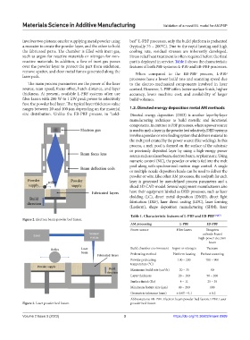
Figure 2. Electron beam-powder bed fusion.
AM processing L‑PBF EB‑PBF
Power source Fiber lasers Tungsten
cathode-based
high-power electron
beam
Build chamber environment Argon or nitrogen Vacuum
Preheating method Platform heating Preheat scanning
Powder preheating 100 – 200 700 – 900
temperature (°C)
3
Maximum build rate (cm /h) 20 – 35 80
Layer thickness 20 – 100 50 – 200
Surface finish (Ra) 4 – 11 25 – 35
Minimum feature size (μm) 40 – 200 100
Geometric tolerance (mm) ± 0.05 – 0.1 ± 0.2
Abbreviations: EB-PBF: Electron beam powder bed fusion; LPBF: Laser
Figure 3. Laser powder bed fusion. powder bed fusion.
Volume 2 Issue 3 (2023) 3 https://doi.org/10.36922/msam.0999