
Page 9 - MSAM-3-2
P. 9
Materials Science in Additive Manufacturing Functional materials for AM
Table 1. Characteristics of each polymer AM process
AM process Printing Raw materials Fabrication mechanism Resolution Resolution Typical build
method (xy [µm]) (thickness [µm]) size (mm )
3
Material extrusion FDM Thermoplastic filaments or Molten material 100 – 150 100 – 200 223×223×305
pellets extrusion
DIW Viscoelastic ink Material extrusion and 100 – 1200 100 – 400 260×220×70
solidification
Meniscus Viscous ink Ink extrusion by 0.05 – 2 - 4×25
printing meniscus contact
Vat photopolymerization SLA Photosensitive polymer resin UV laser curing 6.5 – 25 25 – 300 145×145×175
DLP Photosensitive polymer resin DLP projector curing 35 – 100 25 – 150 140×79×100
CLIP Photosensitive polymer resin Continuous UV curing 75 0.4 – 100 150×80×300
Binder jetting - Powdered materials Drop bonding liquid 100 260 – 380 1800×1000×700
Powder bed fusion SLS Polymer powder Laser sintering 30 – 100 60 – 180 340×340×600
Material jetting Polyjet Thermoset photopolymers Liquid material deposit 42 – 85 16 – 28 294×192×148.6
and UV curing
Abbreviations: AM: Additive manufacturing; CLIP: Continuous liquid interface production; DIW: Direct ink writing; DLP: Digital light processing;
FDM: Fused deposition modeling; SLA: Stereolithography; SLS: Selective laser sintering.
A C
B D E
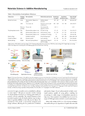
Figure 2. Schematic illustrations of the additive manufacturing process for functional materials. (A) Material extrusion 3D printing; left panel reproduced
21
with permission from Liu et al. (Copyright © 2022 American Chemical Society); center panel reproduced with permission from Hossain et al. (Copyright
16
© 2022 American Chemical Society); right panel reproduced with permission from Lee et al. (Copyright © 2017 American Chemical Society). (B) Vat
23
25
photopolymerization 3D printing; left panel reproduced with permission from Pagac et al. (Copyright © 2018 American Chemical Society); center
27
panel reproduced with permission from Chiappone et al. (Copyright © 2021 American Chemical Society); and right panel reproduced with permission
from Wang et al. (Copyright © 2023 American Chemical Society). (C) Binder jetting; reproduced with permission from Jose et al. (Copyright © 2016
29
28
30
American Chemical Society). (D) Selective laser sintering; reproduced with permission from Ouyang et al. (Copyright © 2022 American Chemical
31
Society). (E) Material jetting; reproduced with permission from Sireesha et al. (Copyright © 2018 RSC Advances).
extruded through a movable nozzle controlled by software and precise shapes. Recent advancements include screw-
to create layers. This process typically involves heating based systems capable of using pellets, enabling the
16
the thermoplastic filament to its melting point within the processing of a wider range of thermoplastic materials in
printer’s extruder assembly. The melted filament is then large sizes. This expansion of capabilities has increased the
precisely deposited onto the build platform layer by layer, scope of FDM applications in both research and industry.
where it quickly solidifies to form the desired object. The
movement of the nozzle is directed by computer-aided Direct ink writing (DIW) is a 3D printing technique
design software, allowing for the production of intricate that enables the precise deposition of liquid-state materials
Volume 3 Issue 2 (2024) 3 doi: 10.36922/msam.3323