
Page 97 - MSAM-4-2
P. 97
Materials Science in Additive Manufacturing Additively manufactured high carbon steel
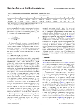
Table 1. Composition of powders and the as‑printed sample determined by XEDS
ID Composition (wt.%)
Fe Si Cr Mo Ni Mn V C* O* N* S*
Powders Bal. 0.69±0.07 2.64±0.19 0.91±0.07 0.89±0.18 0.58±0.30 0.13±0.05 1.48 0.14 0.02 0.001
As-printed Bal. 0.73±0.06 2.77±0.11 0.93±0.09 1.02±0.13 0.47±0.30 0.14±0.07 1.04 0.03 Neg. 0.001
Note: *Determined by LECO combustion analysis following ASTM E1019-18.
Abbreviation: XEDS: X-ray energy-dispersive spectroscopy.
comparison method was used to approximate the volume quenched martensite directly from the as-printed
fraction of retained austenite (V ), from integrated condition. Solutionizing treatment at 950, 1050, or 1075°C
γ
intensities of γ(111) and α(110) diffraction peaks, I γ (111) and for 1 h, followed by water quenching, was also carried out
I α , respectively, using the expression: 29,30 to dissolve cellular dendrites apparent in the as-printed
(110)
condition. Low-temperature tempering of as-printed
samples was carried out with reference to Figure 1A at
1.4 ×I
γ
(111)
=
V I + 1 .4I (I) 125, 175, 200, 250, and 300°C for 3 h to probe the bainitic
γ
transformation as a function of temperature. Finally, a
α
(111)
γ
(110)
combination of cryogenic quenching, solutionizing, and
In Equation I, carbide formation is assumed negligible tempering was carried out to obtain a mixed microstructure
and does not account for any signification volume fraction. consisting of martensite, bainite, and austenite. The
Further microstructural examination of the optimized microhardness of the samples was measured using a LECO
processing parameters was conducted using a scanning LV700 Vickers hardness indenter (LECO Corporation,
electron microscope (Zeiss Ultra 55 SEM; Carl Zeiss AG, United States) following ASTM E92-17 using a load of
Germany) operating at 20 kV equipped with an XEDS 10 kg and dwell time of 10 s. A total of five indents were
detector. performed for each sample to obtain sufficient statistical
confidence.
2.2. LPBF and sample preparation
3. Results
Gas-atomized and sieved powders with a mean particle
size of 53.7 μm were used to fabricate rectangular bars with 3.1. Martensitic transformation
dimensions of 8 × 8 × 100 mm in an SLM 125 system
HL
(Nikon-SLM Solutions, Germany equipped with a Yb-fiber Figure 2A presents the XRD pattern, and Figure 2B displays
laser capable of producing a spot size of 70 μm. Samples the austenitic microstructure characterized by fine cellular
were fabricated directly on a stainless steel 316L substrate dendrites in the as-print specimen produced by LPBF. Qiao
31
preheated to 100°C within an argon atmosphere at oxygen et al. reported that the retained austenite, transforming
concentrations below 0.1%. Laser power, scan speed, to martensite in high-carbon steel after exposure to
hatch spacing, and slice thickness were held constant at cryogenic conditions, exhibited a decrease from 12% after
200 W, 800 mm/s, 120 μm, and 30 μm, respectively, from 2 h to approximately 10% after 48 h. Thus, a soak time of
a cursory study of parameter optimization based on the 2.5 h in LN is reasonable for the majority of the austenite
2
highest relative density. The laser was scanned with 10 mm in the as-printed condition to transform. To explore the
stripe widths at a constant interlayer rotation of 16°. The phase transformation of the austenitic microstructure
rectangular bars were removed from the substrate through observed in the as-printed condition, as-printed samples
wire electric discharge machining (EDM) without stress- were quenched in liquid nitrogen at room temperature
relieving and cross-sectioned using a slow-speed diamond for up to 2.5 h. As displayed in Figure 2A, the intensity of
the austenitic (γ) peak at 43.3° observed for the quenched
saw. Cross-sections were obtained parallel to the build sample is lower than that observed for the as-printed
direction and kept in the as-print condition to characterize sample. The martensitic (M) peak observed just to the
for baseline reference. All cross-sectioned surfaces were right of the γ(111) peak has become the dominant phase
mounted in epoxy resin and metallographically polished after quenching, which indicates that the austenite retained
down to a 1 μm finish and chemically etched with 4% Nital.
at room temperature has transformed into martensite,
Various post-processing treatments were performed approximately 76 vol.%, after quenching in LN . The
2
to document the phase transformations of the as-printed evidence for the transformation of the as-printed austenitic
samples as follows. As-printed samples were quenched microstructure depicted in Figure 2B can be seen in the
in liquid nitrogen (LN ) and held for 2.5 h to produce secondary electron micrograph in Figure 2C. Here, the
2
Volume 4 Issue 2 (2025) 4 doi: 10.36922/MSAM025100011