
Page 33 - MSAM-4-3
P. 33
Materials Science in Additive Manufacturing Numerical simulation of plasma WAAM for Ti-6Al-4V
All components were initially designed in SolidWorks was set to accurately capture the cooling behavior of the
2020 and then meshed in Abaqus CAE 6.14. To optimize assembly and to precisely define the heat source parameters
computational efficiency, the symmetry properties were and cooling parameters.
exploited by modeling only half of the calibration setup. The moving heat source was calibrated using an
To simplify the simulation and facilitate the efficient iterative trial-and-error approach, where the simulation’s
implementation of thermal interactions, the carbon fiber fusion zone shape and temperature profiles were matched
composites support and the alumina wool insulation were against experimental results by adjusting the heat source’s
modeled as a single component. This allowed a single geometric parameters and thermal boundary conditions.
effective contact heat transfer coefficient to be applied to The melt pool dimensions obtained from the
the underside of the baseplate. The cross-section profiles metallurgical analysis were used to define the geometric
of the weld beads were approximated by a second-degree
polynomial fitting, expressed as Equation X. parameters of the Goldak double-ellipsoid heat source.
The width b and depth d of the fusion zone were measured
f (x) = c x + c 0 (X) directly from the micrographs of the weld pool cross-
2
2
The parabolic representation closely approximates sections. The front and rear ellipsoid lengths, a and a , were
r
f
the actual shape of the weld beads, ensuring geometric estimated based on the empirical relationships provided by
20
consistency between the numerical model and the Simufact using Equation XI.
experimental observations. The FE model of the calibration a = b
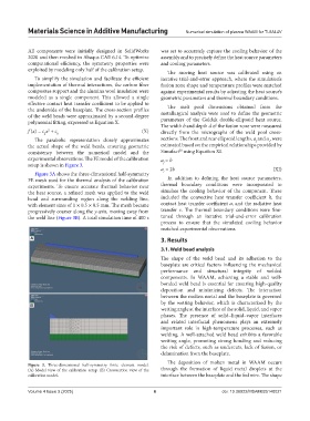
setup is shown in Figure 3. f
a = 2b (XI)
Figure 3A shows the three-dimensional half-symmetry r
FE mesh used for the thermal analysis of the calibration In addition to defining the heat source parameters,
experiments. To ensure accurate thermal behavior near thermal boundary conditions were incorporated to
the heat source, a refined mesh was applied to the weld simulate the cooling behavior of the component. These
bead and surrounding region along the welding line, included the convective heat transfer coefficient h, the
with element sizes of 1 × 0.5 × 0.5 mm. The mesh became contact heat transfer coefficient a, and the radiative heat
progressively coarser along the y-axis, moving away from transfer ε. The thermal boundary conditions were fine-
the weld line (Figure 3B). A total simulation time of 400 s tuned through an iterative trial-and-error calibration
process to ensure that the simulated cooling behavior
matched experimental observations.
A 3. Results
3.1. Weld bead analysis
The shape of the weld bead and its adhesion to the
baseplate are critical factors influencing the mechanical
performance and structural integrity of welded
components. In WAAM, achieving a stable and well-
bonded weld bead is essential for ensuring high-quality
deposition and minimizing defects. The interaction
between the molten metal and the baseplate is governed
by the wetting behavior, which is characterized by the
B
wetting angle at the interface of the solid, liquid, and vapor
phases. The presence of solid–liquid–vapor interfaces
and related interfacial phenomena plays an extremely
important role in high-temperature processes, such as
welding. A well-attached weld bead exhibits a favorable
wetting angle, promoting strong bonding and reducing
the risk of defects, such as undercuts, lack of fusion, or
delamination from the baseplate.
The deposition of molten metal in WAAM occurs
Figure 3. Three-dimensional half-symmetry finite element model.
(A) Model view of the calibration setup. (B) Crosssection view of the through the formation of liquid metal droplets at the
calibration model. interface between the baseplate and the fed wire. The shape
Volume 4 Issue 3 (2025) 6 doi: 10.36922/MSAM025140021