
Page 29 - MSAM-4-3
P. 29
Materials Science in Additive Manufacturing Numerical simulation of plasma WAAM for Ti-6Al-4V
Various arc processes can be used as the energy 2. Materials and methods
source in WAAM, including gas metal arc welding, gas
5
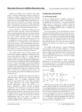
tungsten arc welding, and plasma arc welding. A defining 2.1. Heat source model
characteristic of these welding processes is the localized In the arc welding module of Simufact Welding 8.0,
heat input from a moving high-energy-density heat source, the Goldak double-ellipsoid model is implemented as
which leads to the formation of transient temperature the default heat source (Figure 1). This moving double-
fields in the material. The evolution of the temperature ellipsoid model is widely used to simulate various arc
fields is influenced by the thermo-physical properties of welding techniques, including gas metal arc welding, gas
the material, the path strategy, and welding parameters. 6 tungsten arc welding, shielded metal arc welding, and
Because WAAM is a multi-layer welding process in submerged arc welding. 20
which the feedstock material is melted and deposited in The thermal analysis of the WAAM process involves
layers, the previously deposited near-net-shape structure solving a heat transfer problem with a moving heat source.
is repeatedly remelted and reheated with each new layer. The heat source mathematically describes the heat transfer
The cyclic thermal exposure induces non-uniform from the arc to the melt pool, characterizing the energy
thermal expansion in both the deposited material and the distribution within the weld pool. The goal of this model
surrounding base material, leading to the formation of is to approximate the isothermal surface of the actual
residual stresses and distortion fields. The deformation melt pool and the heat flow across that surface with high
7
and residual stresses of WAAM-produced components, accuracy. The effects of the melt pool are considered
particularly those made from titanium and steel, have been indirectly.
studied extensively. 8-11 Residual stresses influence several The Goldak model describes a Gaussian distributed
critical failure mechanisms, including fracture and fatigue heat generation per unit volume defined in a moving
properties, stress corrosion cracking, and distortion. 12 reference frame. A local Cartesian coordinate system (x, y,
The complex thermal history of parts produced with and z) is defined at the weld point with the x-axis aligned
WAAM poses significant challenges in predicting residual with the welding direction and the z-axis perpendicular
stresses and distortion fields. As a result, numerical to the welding torch. The heat source moves at a constant
process simulation has emerged as a feasible and cost- velocity v along the x-axis.
effective method for predicting temperature distributions, To account for the asymmetric nature of the heat
distortions, and stress fields in the parts during the printing distribution in the melt pool, two power distribution
process. 13,14 However, the quality of the process simulation functions q and q (W/m³) are used for the front and rear
f
r
strongly depends on the mathematical description of the semi-ellipsoidal regions, respectively. The power density
19
heat source. The configuration of the heat source, including distribution is defined in Equation I:
parameter adjustments and thermal conductivity settings, 63 Q
(
,,
plays a critical role in determining the accuracy of qx yz t , ) =
simulated results, particularly in predicting distortions and ππ bd
residual stresses. 15 f ( 3 xvt) 2 3 y 2 z 3 2
−
f ⋅ exp − − − ffor xvt
>
In this study, a trial-and-error approach is used to a f a 2 f b 2 d
2
calibrate the numerical heat source by iteratively adjusting 2 (I)
−
parameters until the simulated temperature fields f r ⋅exp − ( 3 xvt) − 3 y 2 − z 3 2 for xvt<
16
match the experimental data. Since these parameters a r a r 2 b 2 d
2
are highly dependent on the welding conditions, their
accurate determination requires the solution of an Where Q is the total power (W), a and a are the front
f
r
inverse optimization problem through appropriate and rear ellipsoid lengths (m), b is the ellipsoid width (m),
experiments. The calibration process involves refining d is the ellipsoid depth (m), and f and f are the fractions of
17
f
r
multiple parameters to achieve a validated temperature heat distributed in the front and rear ellipsoids, respectively.
field, ensuring consistency with thermal cycles recorded The front and rear fractions satisfy the condition f + f = 2
f
r
by thermocouples and the weld pool geometry observed to ensure continuity of the volumetric heat source. Goldak
in light-optical micrographs. Several variants of Goldak’s et al. suggest default values that set the front fraction to
19
18
double-ellipsoid heat source model are tested and f = 0.6 if experimental data are insufficient. These fractions
19
r
compared within Simufact Welding 8.0, allowing for a can be computed automatically when the geometric
systematic validation of the numerical model. parameters are known (Equation II). 21,22
Volume 4 Issue 3 (2025) 2 doi: 10.36922/MSAM025140021