
Page 66 - TD-4-2
P. 66
Tumor Discovery Glioblastoma treating fields system
A
B C D
E F G
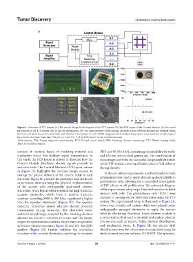
Figure 1. Overview of TTF system. (A) The overall design block diagram of the TTF system. (B) The PCB layout of the Control Module. (C) An actual
photograph of the TTF system used in the cell experiments. (D) The measurements of the ceramic electrode across different frequencies; the inset shows
the front and back of a ceramic electrode, with the back silver plated. (E and F) SEM images and EDS analysis showing the cross-sectional morphology of
the ceramic electrode. Scale bars: 100 µm (e); 2 µm (f). (G) The XRD pattern of the ceramic electrode.
Abbreviations: EDS: Energy dispersive spectrometry; PCB: Printed circuit board; SEM: Scanning electron microscopy; TTF: Tumor treating fields;
XRD: X-ray diffractometry.
consists of multiple layers of insulating material and PDF card 00-056-1034, confirming the suitability for stable
conductive traces that facilitate signal transmission. In and efficient electric field generation. The combination of
this study, the PCB layout is shown to illustrate how the these images confirms the successful design and fabrication
Control Module distributes electric signals precisely to of the TTF system, ensuring effective electric field delivery
each electrode. The Control Module’s PCB layout, shown during therapy.
in Figure 1B, highlights the intricate design needed to In the cell culture experiments, a well-defined electrode
manage the precise delivery of the electric fields to each
electrode. Figure 1C presents the prototype used in the cell arrangement was used to apply alternating electric fields to
experiments, demonstrating the physical implementation glioblastoma cells, allowing for a controlled investigation
of the system with orthogonally positioned ceramic of TTF effects on cell proliferation. The schematic diagram
electrodes. A key feature of the system is the high-dielectric of the experimental setup helps illustrate how electric fields
ceramic electrodes, which have a relative dielectric interact with cells. The glioblastoma cells (U251) were
constant exceeding 8000 at 200 kHz, significantly higher exposed to varying electric field intensities using the TTF
than the reported electrodes (Figure 1D). The superior system. The experimental setup is illustrated in Figure 2A,
6
dielectric properties ensure effective electric potential where four circular cell culture slides were placed under
transmission during treatment. The electrode’s cross- orthogonally arranged electrodes to apply the electric
sectional morphology, analyzed by the scanning electron fields in alternating directions. Finite element analysis is
microscope, reveals a uniform structure, and the energy a numerical method used to simulate and analyze physical
dispersive spectrometer confirms the primary composition phenomena such as electric fields, thermal distribution,
as barium titanate zirconate (Figure 1E and 1F). The XRD and mechanical stress. In Figure 2B, the electric field
analysis (Figure 1G) further validates the crystalline distribution across the culture area was simulated using the
structure of the ceramic electrodes, matching the standard finite element analysis software (COMSOL Multiphysics),
Volume 4 Issue 2 (2025) 58 doi: 10.36922/td.7171