
Page 252 - AJWEP-22-4
P. 252
Mohamed and Katambara
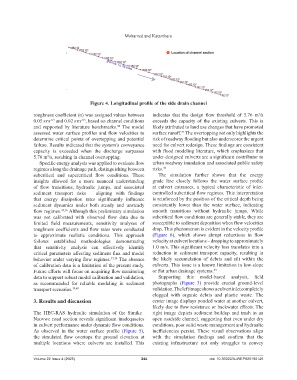
Figure 4. Longitudinal profile of the side drain channel
roughness coefficient (n) was assigned values between indicates that the design flow threshold of 5.76 m /s
3
0.05 sm and 0.02 sm , based on channel conditions exceeds the capacity of the existing culverts. This is
.
-1/3
.
-1/3
and supported by literature benchmarks. The model likely attributed to land use changes that have promoted
34
assessed water surface profiles and flow velocities to surface runoff. The overtopping not only highlights the
41
determine critical points of overtopping and potential risk of roadway flooding but also underscores the urgent
failure. Results indicated that the system’s conveyance need for culvert redesign. These findings are consistent
capacity is exceeded when the discharge surpasses with flood modeling literature, which emphasizes that
5.76 m /s, resulting in channel overtopping. under-designed culverts are a significant contributor to
3
Specific energy analysis was applied to evaluate flow urban roadway inundation and associated public safety
regimes along the drainage path, distinguishing between risks. 42
subcritical and supercritical flow conditions. These The simulation further shows that the energy
insights allowed for a more nuanced understanding grade line closely follows the water surface profile
of flow transitions, hydraulic jumps, and associated at culvert entrances, a typical characteristic of inlet-
sediment transport risks – aligning with findings controlled subcritical flow regimes. This interpretation
that energy dissipation rates significantly influence is reinforced by the position of the critical depth being
sediment dynamics under both steady and unsteady consistently lower than the water surface, indicating
flow regimes. 35,36 Although this preliminary simulation smooth transitions without hydraulic jumps. While
was not calibrated with observed flow data due to subcritical flow conditions are generally stable, they are
limited field measurements, sensitivity analyses of susceptible to sediment deposition when flow velocities
roughness coefficients and flow rates were conducted drop. This phenomenon is evident in the velocity profile
to approximate realistic conditions. This approach (Figure 6), which shows abrupt reductions in flow
follows established methodologies demonstrating velocity at culvert locations – dropping to approximately
that sensitivity analysis can effectively identify 1.0 m/s. This significant velocity loss translates into a
critical parameters affecting sediment flux and model reduction in sediment transport capacity, resulting in
behavior under varying flow regimes. 37,38 The absence the likely accumulation of debris and silt within the
of calibration data is a limitation of the present study. culverts. This issue is a known limitation in low-slope
Future efforts will focus on acquiring flow monitoring or flat urban drainage systems. 43
data to support robust model calibration and validation, Supporting this model-based analysis, field
as recommended for reliable modeling in sediment photographs (Figure 3) provide crucial ground-level
transport scenarios. 39,40 validation. The left image shows a culvert inlet completely
clogged with organic debris and plastic waste. The
3. Results and discussion center image displays ponded water at another culvert,
likely due to flow resistance or backwater effects. The
The HEC-RAS hydraulic simulation of the Simike– right image depicts sediment buildup and trash in an
Nzovwe road section reveals significant inadequacies open roadside channel, suggesting that even under dry
in culvert performance under dynamic flow conditions. conditions, poor solid waste management and hydraulic
As observed in the water surface profile (Figure 5), inefficiencies persist. These visual observations align
the simulated flow overtops the ground elevation at with the simulation findings and confirm that the
multiple locations where culverts are installed. This existing infrastructure not only struggles to convey
Volume 22 Issue 4 (2025) 244 doi: 10.36922/AJWEP025190146