
Page 161 - AJWEP-v22i2
P. 161
Enhanced renewable integration for power system stability
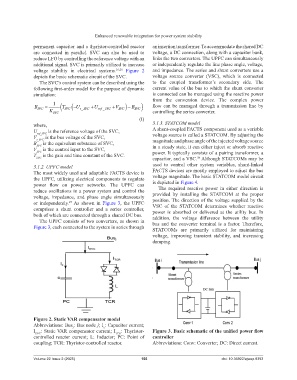
permanent capacitor and a thyristor-controlled reactor an insertion transformer. To accommodate the shared DC
are connected in parallel. SVC can also be used to voltage, a DC connection, along with a capacitor bank,
reduce LFO by controlling the reference voltage with an links the two converters. The UPFC can simultaneously
additional signal. SVC is primarily utilized to increase or independently regulate the line phase angle, voltage,
voltage stability in electrical systems. 25,26 Figure 2 and impedance. The series and shunt converters use a
depicts the basic schematic circuit of the SVC. voltage source converter (VSC), which is connected
The SVC’s control system can be described using the to the coupled transformer’s secondary side. The
following first-order model for the purpose of dynamic current value of the bus to which the shunt converter
simulation: is connected can be managed using the reactive power
from the conversion device. The complex power
B SVC K 1 T U t SVC_ U ref _ SVC V B SVC flow can be managed through a transmission line by
SVC
SVC
controlling the series converter.
SVC (I)
where, 3.1.3. STATCOM model
U ref_SVC is the reference voltage of the SVC, A shunt-coupled FACTS component used as a variable
V t_SVC is the bus voltage of the SVC, voltage source is called a STATCOM. By adjusting the
B SVC is the equivalent substance of SVC, magnitude and phase angle of the injected voltage source
V SVC is the control input to the SVC, in a steady state, it can either inject or absorb reactive
T is the gain and time constant of the SVC. power. It typically consists of a pairing transformer, a
SVC capacitor, and a VSC. Although STATCOMs may be
28
3.1.2. UPFC model used to control other system variables, shunt-linked
The most widely used and adaptable FACTS device is FACTS devices are mostly employed to adjust the bus
the UPFC, utilizing electrical components to regulate voltage magnitude. The basic STATCOM model circuit
power flow on power networks. The UPFC can is depicted in Figure 4.
reduce oscillations in a power system and control the The required reactive power in either direction is
voltage, impedance, and phase angle simultaneously provided by installing the STATCOM at the proper
or independently. As shown in Figure 3, the UPFC position. The direction of the voltage supplied by the
27
VSC of the STATCOM determines whether reactive
comprises a shunt controller and a series controller, power is absorbed or delivered at the utility bus. In
both of which are connected through a shared DC bus. addition, the voltage difference between the utility
The UPFC consists of two converters, as shown in bus and the converter terminal is a factor. Therefore,
Figure 3, each connected to the system in series through STATCOMs are primarily utilized for maintaining
voltage, improving transient stability, and increasing
damping.
Figure 2. Static VAR compensator model
Abbreviations: Bus : Bus node j; I : Capacitor current;
c
J
I SVC : Static VAR compensator current; I TCR : Thyristor- Figure 3. Basic schematic of the unified power flow
controlled reactor current; L: Inductor; PC: Point of controller
coupling; TCR: Thyristor-controlled reactor. Abbreviations: Conv: Converter; DC: Direct current.
Volume 22 Issue 2 (2025) 155 doi: 10.36922/ajwep.8393