
Page 164 - AJWEP-v22i2
P. 164
Reddy and Kumar
( )( ) sources such as thermal generators, wind power, small
P ij , ij , (V) hydro, and photovoltaic arrays. To enhance power
ij, ( ij , )( ij , ) system stability and efficiency, FACTS controllers are
where, strategically placed at weak buses and transmission lines.
τ ij, is the total amount of pheromone between nodes The optimal locations for FACTS device installation are
i and j, identified based on system stability analysis. 32,33 SVCs
α is the parameter controlling the impact of τ, i, j, are employed to regulate reactive power distribution
ƞ is the desirability of nodes i and j (usually 1/d ), among buses, while SSSCs adjust transmission
i,j
i,j
β controls the impact of η . line impedance to control real power flow. UPFCs
i,j
The pheromone value varies as the arc (i, j) is crossed, improve voltage regulation and power flow capacity
following the equation: in transmission lines, whereas STATCOMs stabilize
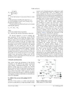
voltages and mitigate oscillations. By positioning
( 1 ) (VI)
ij, ij, ij, FACTS devices at weak lines and buses, the system
effectively manages reactive power flow, prevents
where, transmission line overloads, and enhances overall grid
ρ is the rate of pheromone evaporation, reliability. Figure 6 illustrates the architecture of the
stands for the amount of pheromone deposited. IEEE-30 bus system with FACTS controllers.
ij,
The hit-trial approach is used to initialize the The IEEE-30 bus system, incorporating renewable
gain parameters of the alternating current FACTS energy sources such as wind, solar, and small hydro,
controllers, whereas ACO selects the optimal values. consisted of six generators and 41 transmission lines.
The gain values of the four FACTS controllers in ACO The integration of these renewable sources introduced
depend on the locations of the ants. An update in the voltage fluctuations and power flow variations,
ant’s position causes the associated gain values of the necessitating the strategic placement of FACTS
alternating current FACTS controllers to be updated controllers for enhanced stability. Branch 15 was
accordingly. For each updated gain value, the entire identified as an optimal location for an SSSC based on
model is executed, and the resulting deviations in rotor the L sensitivity index, helping to regulate real power
mn
angle, angular speed, and generator voltages – regarded flow amid varying renewable generations. Similarly,
as the objective function – are recorded. The gain that buses 26 and 29 experienced significant voltage
minimizes the objective function the most, or the gain variations due to fluctuating renewable outputs, as
that results in the smallest deviations in rotor angle, indicated by the Fast Voltage Stability Index (FVSI). To
angular speed, and generator voltage across all four mitigate these instabilities, an SVC was installed on bus
machines, is chosen as the final FACTS gain once each 29. Voltage fluctuations caused by variable renewable
iteration has been completed. power injection were detected by the voltage sensitivity
5. Results and discussion
This section verifies the performance of the FACTS
controllers on the IEEE-30 bus system constructed
using MATrix LABoratory/SIMULINK. The main
objective of this work was to examine these FACTS
devices within the IEEE-30 bus system and assess their
performance. To reduce oscillations, FACTS devices
such as STATCOM, SSSC, UPFC, and SVC are used.
This section discusses the efficacy of FACTS controllers
in dampening oscillations both with and without the use
of the ACO algorithm.
5.1. IEEE-30 bus system with multiple FACTS
devices
The IEEE 30-bus system is a widely used benchmark Figure 6. IEEE-30 bus system
for power system analysis, integrating multiple energy Abbreviation: PV: Photovoltaic.
Volume 22 Issue 2 (2025) 158 doi: 10.36922/ajwep.8393