
Page 93 - DP-2-2
P. 93
Design+ Closed-form solution for pressurized obround shells
center of this section was required in the analysis. The
difference between the two was small, and their average
provides a good approximation.
The hoop stress distribution of Section B was similar
to that of Section D, that is, the tension stress occurred at
the outer surface. This suggests that the section where the
hoop tensile stress shifted from the inner surface to the
outer surface is located between section C and section B.
In section B, the radial stress obtained using either
Equation XXIII or XXVI was inaccurate. Lame’s solution
provided a better result, even though this section is not a
symmetry plane (Figure 8).
The first and last terms in Equations XXII and XXIII
are independent functions of θ. They are axisymmetric
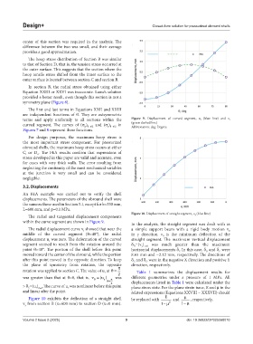
terms and apply uniformly to all sections within the Figure 9. Displacement of curved segment, u r (blue line) and v t
curved segment. The curves of (σ ) and (σ ) in (green dashed line)
Abbreviation: deg: Degree.
r θ=π/2
θ θ=π/2
Figures 7 and 8 represent these functions.
For design purposes, the maximum hoop stress is
the most important stress component. For pressurized
obround shells, the maximum hoop stress occurs at either
C or D . The FEA results confirm that expressions of
o
i
stress developed in this paper are valid and accurate, even
for cases with very thick walls. The error resulting from
neglecting the continuity of the most mechanical variables
at the junction is very small and can be considered
negligible.
3.2. Displacements
An FEA example was carried out to verify the shell
displacements. The parameters of the obround shell were
the same as those used in Section 3.1, except for b=330 mm,
L=600 mm, and p=0.1 MPa.
Figure 10. Displacement of straight segment, v y (blue line)
The radial and tangential displacement components
within the curve segment are shown in Figure 9. In the analysis, the straight segment was dealt with as
The radial displacement curve v showed that near the a simple support beam with a rigid body motion v
t
0
middle of the curved segment (θ≈48°), the radial in y direction. v is the minimum deflection of the
0
displacement u was zero. The deformation of the curved straight segment. The maximum vertical displacement
r
segment seemed to result from the rotation around the δ =(v ) was much greater than the maximum
y x=0
D
point θ≈48°. The portion of the shell before this point horizontal displacements δ In this case, δ and δ were
C
D
C
moved toward the center of the obround, while the portion 8.65 mm and −2.12 mm, respectively. The directions of
after this point moved in the opposite direction. To keep δ and δ were in the negative X direction and positive Y
D
C
the plane of symmetry from rotation, the opposite direction, respectively.
rotation was applied to section C. The value of u at = 2 Table 1 summarizes the displacement results for
r
u
was greater than that at θ=0, that is, v = () was different geometries under a pressure of 1 MPa. All
0
r
= 2 displacements listed in Table 1 were calculated under the
> δ =(u ) . The curve of u was nonlinear before this point plane stress state. For the plane strain issue, E and μ in the
C
r
r θ=0
and linear after the point. related expressions (Equations XXVIII – XXXVII) should
Figure 10 exhibits the deflection of a straight shell be replaced with E and µ , respectively.
v from section B (x=600 mm) to section D (x=0 mm). 1− µ 2 1− µ
y
Volume 2 Issue 2 (2025) 9 doi: 10.36922/DP025060010