
Page 94 - DP-2-2
P. 94
Design+ Closed-form solution for pressurized obround shells
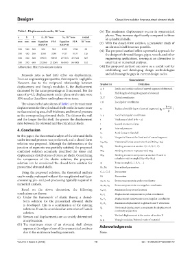
Table 1. Displacement results, 10 mm (iv) The maximum displacement occurs in symmetrical
−3
planes. They increase significantly compared to those
a b L δC, 10 mm δD, 10 mm round of cylindrical shells.
−4
−4
mm mm mm Equation FEA Equation FEA 10 mm (v) With the closed-form solution, a parameter study of
−3
XXXVII XXXVII
an obround shell becomes possible.
300 500 380 562 563 1529 1530 69 (vi) The proposed method offers a powerful approach for
300 400 380 3388 3389 9137 9137 126 the design of obround flanges, pipes, vessels, and other
300 330 380 98933 98933 277333 277333 387 engineering applications, serving as an alternative to
300 330 600 212069 212069 864805 864805 524 empirical or numerical analyses.
Abbreviation: FEA: Finite element analysis (vii) The proposed method can serve as a useful tool for
establishing and developing design methodologies
Poisson’s ratio μ had little effect on displacement. and addressing the gaps in current design codes.
From an engineering perspective, this impact is negligible. Nomenclature
However, due to the reciprocal relationship between Symbol (s) Definition
displacement and Young’s modulus E, the displacement a, b Inside and outside radius of curved segment of obround
decreased by the same percentage as E increased. For the
case of μ=0.3, displacements under plane strain state were L Half-length of straight segment of obround
10% smaller than those under plane stress issue. X, Y Global coordinates
The values in the last column of Table 1 are the maximum r, θ Local polar coordinates
+
displacements for the cylindrical shells with the same inner r0 Radius of middle layer of curved segment ( r = ba )
0
surface enclosing area, shell thickness, and internal pressure 2
as the corresponding obround shells. The thinner the wall x, y Local rectangular coordinates
and the longer the flat shell, the greater the displacement t Thickness of shell (t=b − a)
ratio between the obround and the cylindrical shells. I Second moment of area
4. Conclusion p Internal pressure
Fx Axial forces in flat shell
In this paper, the theoretical analysis of the obround shells Tangential force at the fixed end of curved segment
under internal pressure was performed, and a closed-form Fy
solution was proposed. Although the deformation at the FAy, FBy Transversal forces at sections A and B (FAy=FBy)
junction of segments was partially satisfied, the proposed M i Bending moment at section i (i=A, B, C, D)
combined solution accurately described the stress and MB1 Bending moment in pressurized ring
displacement distributions of obround shells. Considering MB2 Bending moment component at section B used to
the uniqueness of the elastic solution, the proposed calculate rotation angle (MB2=MB−MB1)
solution can be considered the closed-form solution for α i Rotation angle (i=1, 2, 3, …)
pressurized obround shells. N1, N2 Size-related parameters
Using the proposed solution, the theoretical analysis C_1, C_2 Parameters
can be easily performed without the complicated and time- Ki Parameters
consuming pre- and post-processing typically required in σθ, σr, τrθ Stress components in polar coordinates
numerical analysis. σx, σy, τxy Stress components in rectangular coordinates
Based on the above discussion, the following C i , D o Maximum hoop stress location
conclusions are drawn: u r , v t Displacement components in polar coordinates
(i) Under the framework of elastic theory, a closed- Displacement components in rectangular coordinates
form solution for the pressurized obround shells u x , v y Maximum displacement in global X and Y directions
is developed. This is a combination of the existing δ C , δ D
solutions. It can be considered an extension of Lame’s δ 0 Horizontal displacement to maintain the displacement
continuity at junction
solution.
(ii) Stresses and displacements are accurately determined v 0 Vertical displacement at the center of section B
at any location. E, μ Young’s modulus, Poisson’s ratio of material
(iii) The maximum stress of an obround shell always Acknowledgments
appears at the edges of one of the symmetrical sections
due to the maximum bending moments. None.
Volume 2 Issue 2 (2025) 10 doi: 10.36922/DP025060010