
Page 10 - ESAM-1-1
P. 10
Engineering Science in
Additive Manufacturing ML in MAM monitoring and control through images
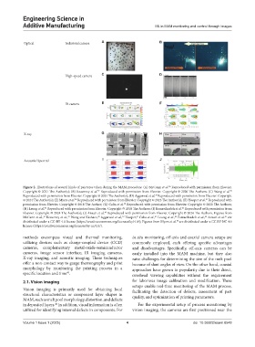
Optical Industrial camera A B
High-speed camera C D
IR camera E F
X-ray G H
Acoustic/ Spectral I J
Figure 2. Illustrations of several kinds of paictures taken during the MAM procedure. (A) McCann et al. Reproduced with permission from Elsevier.
36
Copyright © 2021 The Author(s); (B) Keaveney et al. Reproduced with permission from Elsevier. Copyright © 2020 The Authors; (C) Wang et al.
37
38
Reproduced with permission from Elsevier. Copyright © 2024 The Author(s); (D) Aggarwal et al. Reproduced with permission from Elsevier. Copyright
39
© 2024 The Author(s); (E) Myers et al. Reproduced with permission from Elsevier. Copyright © 2023 The Author(s); (F) Hooper et al. Reproduced with
40
41
permission from Elsevier. Copyright © 2018 The Author; (G) Calta et al. Reproduced with permission from Elsevier. Copyright © 2020 The Authors;
42
(H) Leung et al. Reproduced with permission from Elsevier. Copyright © 2018 The Authors; (I) Esmaeilzadeh et al. Reproduced with permission from
43
44
Elsevier. Copyright © 2024 The Author(s); (J) Ansari et al. Reproduced with permission from Elsevier. Copyright © 2024 The Authors. Figures from
45
McCann et al., Keaveney et al., Wang and Kashaev, Aggarwal et al., Hooper, Calta et al., Leung et al., Esmaeilzadeh et al., Ansari et al. are
37
43
44
45
42
38
39
41
36
distributed under a CC-BY 4.0 license (https://creativecommons.org/licenses/by/4.0/); Figures from Myers et al. are distributed under a CC BY-NC 4.0
40
license (https://creativecommons.org/licenses/by-nc/4.0/).
methods encompass visual and thermal monitoring, in situ monitoring, off-axis and coaxial camera setups are
utilizing devices such as charge-coupled device (CCD) commonly employed, each offering specific advantages
cameras, complementary metal-oxide-semiconductor and disadvantages. Specifically, off-axis cameras can be
cameras, image sensor interface, IR imaging cameras, easily installed into the MAM machine, but they also
X-ray imaging, and acoustic imaging. These techniques raise challenges for determining the size of the melt pool
offer a non-contact way to gauge thermography and print because of slant angles of view. On the other hand, coaxial
morphology by monitoring the printing process in a approaches have grown in popularity due to their direct,
specific location and time . overhead viewing capabilities without the requirement
40
2.1. Vision imaging for laborious image calibration and modification. These
setups enable real-time monitoring of the MAM process,
Vision imaging is primarily used for obtaining local facilitating the detection of defects, assessment of part
structural characteristics or component layer shapes in quality, and optimization of printing parameters.
MAM, such as melt pool morphology, distortion, and defects
46
in deposited layers. In addition, visual information is often For the experimental setup of process monitoring by
utilized for identifying internal defects in components. For vision imaging, the cameras are first positioned near the
Volume 1 Issue 1 (2025) 4 doi: 10.36922/esam.8548