
Page 12 - ESAM-1-1
P. 12
Engineering Science in
Additive Manufacturing ML in MAM monitoring and control through images
signatures from IR images during LPBF printing, such as sub-surface flaws and distinctive features of the melt
the temperature gradient and standard deviations of the pool can be found. Forien et al. utilized an ex situ X-ray
59
melt pool, establishing strong correlations with the surface radiography imaging technique to detect pores during the
roughness of printed samples. Thermography sensing LPBF process, correlating X-ray images with thermal images
proves to work well for identifying internal or external for enhanced defect identification. In the DED process,
flaws in MAM due to its real-time anomaly presentation. researchers have integrated synchrotron X-ray imaging
51
Researchers like Krauss et al. have leveraged layer-wise to observe the sub-surface defects like cracks and pores.
57
60
temperature distributions to identify hot spots early in the Furthermore, high-speed cameras and X-ray imaging have
LPBF process, aiming to prevent interruptions. Internal been used by researchers to track the melt pool as metal
61
defect recognition is often based on thermal information, particles are being laser-melted. The capture of vital
where the anomalies in temperature distribution across data, including melt pool dynamics, changes, and vapor
layers reflect defects such as pores, inclusions, and spatter. depression development, is possible by this integration,
The experimental setup and procedure for enhancing the understanding of the MAM process.
monitoring MAM using vision-based imaging appear Compared to vision light-based techniques, the
to be straightforward and reproducible. The necessary experimental setup and procedure for X-ray-based in situ
components, including the camera, computer system, monitoring of MAM are more intricate due to the utilization
and controlled environment, are readily available in most of specialized X-ray equipment and image processing
laboratory settings. The procedure comprises standard software. Precise calibration of the X-ray source as well as
steps such as sample preparation, imaging, and data the detector is crucial to ensure the accuracy of imaging
analysis. However, the accuracy and reliability of the results results. Moreover, handling radiation sources mandates
may hinge on factors like lighting conditions, camera strict adherence to safety protocols to ensure researcher
calibration, and sample handling. Ensuring consistency in safety and maintain the integrity of the experiment.
these parameters is crucial to guarantee the reproducibility Although X-ray-based image monitoring has advanced
and validity of the experimental findings. technical demands, the procedure remains reproducible
with proper training and expertise. Challenges may arise
2.2. X-ray imaging in optimizing imaging parameters, deciphering complex
X-ray imaging is a real-time, in situ technique for tracking X-ray data, and maintaining consistency in sample
changes in materials or systems. This monitoring technique positioning.
operates on the premise that X-rays penetrate materials,
interact with them, and provide insights into the internal 2.3. Acoustic imaging
structure, composition, and properties by detecting X-ray With benefits including quick dynamic responses,
absorption, scattering, and diffraction within the material. adaptable sensor configurations, and lower hardware
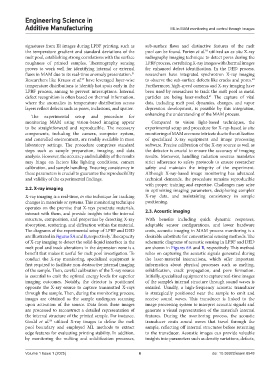
The diagrams of the experimental setup of LPBF and DED costs, acoustic imaging in MAM process monitoring is a
are illustrated in Figures 5A and B, respectively. The capacity desirable substitute for conventional sensing methods. The
of X-ray imaging to detect the solid-liquid interface in the schematic diagrams of acoustic sensing in LPBF and DED
melt pool and track alterations in the depression zone is a are shown in Figures 6A and B, respectively. This method
benefit that makes it useful for melt pool investigation. To relies on capturing the acoustic signals generated during
conduct the X-ray monitoring, specialized equipment is the laser-material interactions, which offer important
first required to facilitate non-destructive internal imaging information about physical processes such as melting,
of the sample. Then, careful calibration of the X-ray source solidification, crack propagation, and pore formation.
is essential to emit the optimal energy levels for superior Initially, specialized equipment to capture real-time images
imaging outcomes. Notably, the detector is positioned of the sample’s internal structure through sound waves is
opposite the X-ray source to capture transmitted X-rays entailed. Usually, a high-frequency acoustic transducer
through the sample. Then, during the monitoring process, is strategically positioned near the sample to emit and
images are obtained as the sample undergoes scanning receive sound waves. This transducer is linked to the
upon activation of the source. Data from these images image processing system to interpret acoustic signals and
are processed to reconstruct a detailed representation of generate a visual representation of the material’s internal
the internal structure of the printed sample. For instance, features. During the monitoring process, the acoustic
Gould et al. utilized X-ray images to define the melt transducer emits sound waves that travel through the
58
pool boundary and employed ML methods to extract sample, reflecting off internal structures before returning
edge features for evaluating printing stability. In addition, to the transducer. Acoustic images can provide valuable
by monitoring the melting and solidification processes, insights into parameters such as density variations, defects,
Volume 1 Issue 1 (2025) 6 doi: 10.36922/esam.8548