
Page 61 - IJAMD-2-3
P. 61
International Journal of AI for
Materials and Design Intelligent interactive textile in healthcare
process (Figure S2). The combination of beige, redwood, the camera captures the hand image, and the deep learning
and blue-grey was selected by stakeholders and is shown model identifies 21 corresponding landmark points. These
in Figure 2C. Using this palette, three knitted fabric wall landmarks – represented by their (x, y) coordinates – are
panels were fabricated and subsequently installed at the analyzed by the self-developed algorithm, which identifies
WTSDHC, as shown in Figure 2D. the gesture as “good” based on the relative positions and
angles between landmark points. This classification is
4.2. Integration of illuminative fabrics into an processed using simple state machine logic and converted
AI-based system into encoded serial data. The data are transmitted to the
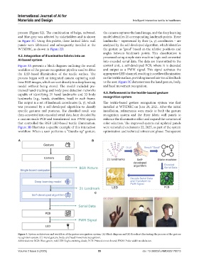
Figure 3A presents a block diagram outlining the overall control unit, a self-developed PCB, where it is decoded
workflow of the gesture recognition pipeline used to drive and output as a PWM signal. This signal activates the
the LED-based illumination of the textile surface. The appropriate LED channel, resulting in a yellow illumination
process began with an integrated camera capturing real- on the textile surface, providing immediate visual feedback
time BGR images, which are sent directly to a deep learning to the user. Figure 3C demonstrates the hand gesture, body,
model without being stored. The model included pre- and head movement recognition.
trained hand-tracking and body pose detection networks
capable of identifying 21 hand landmarks and 33 body 4.3. Refinement in the textile-based gesture
landmarks (e.g., hands, shoulders, head) in each frame. recognition system
The output is a set of landmark coordinates (x, y), which The textile-based gesture recognition system was first
was processed by a self-developed algorithm to classify installed at WTSDHC on June 29, 2021. After the initial
specific gestures and postures. The classified result was installation, refinements were made to both the gesture
then converted into encoded serial data, later decoded by recognition system and the three fabric wall panels to
a custom-made PCB and transformed into PWM signals enhance the illuminative effect and expand the variation of
that controlled the RGB LED-based textile illumination. color selection. The improved system and updated panels
Figure 3B illustrates a specific example of this interaction were reinstalled on January 22, 2025, as part of the system
workflow. When a user performs a “thumbs up” gesture, optimization and technical refinement phase. Transparent
A B
C
Figure 3. System architecture and workflow of the gesture recognition system. (A) Block diagram and (B) flowchart illustrating the process of the gesture
recognition system. (C) Hand gesture, body, and head movement recognition.
Abbreviations: BGR: Blue, green, red; LED: Light-emitting diode; PCB: Printed circuit board; PWM: Pulse width modulation.
Volume 2 Issue 3 (2025) 55 doi: 10.36922/IJAMD025170013