
Page 307 - IJB-10-1
P. 307
International Journal of Bioprinting Low-cost quad-extrusion 3D bioprinting system
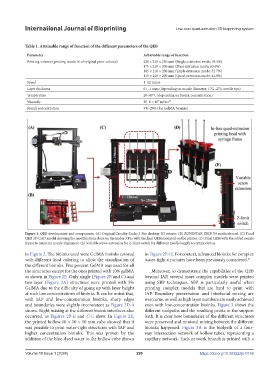
Table 1. Attainable range of function of the different parameters of the QEB
Parameter Achievable range of function
Printing volume (printing mode; % of original print volume) 220 × 210 × 250 mm (Single extrusion mode; 95.5%)
175 × 210 × 200 mm (Dual extrusion mode; 63.6%)
145 × 210 × 200 mm (Triple extrusion mode; 52.7%)
115 × 210 × 200 mm (Quad-extrusion mode; 41.8%)
Speed 1–12 mm/s
Layer thickness 0.1–1 mm (depending on nozzle diameter; 17G–27G needle tips)
Temperature 20–40°C (depending on bioink concentration)
7
Viscosity 30–6 × 10 mPa·s 45
Bioink concentration 3%–20% (for GelMA bioinks)
Figure 1. QEB development and components. (A) Original Creality Ender 3 Pro desktop 3D printer. (B) ZONESTAR ZRIB V6 motherboard. (C) Final
QEB 3D CAD model showing the modifications done on the Ender 3 Pro with the final QEH mounted on the printer. (D) Final QEH with the added nozzle
frame to maintain nozzle alignment. (E) Variable screw extension for Z-limit switch for different needle length accommodation.
in Figure 2. The bioinks used were GelMA bioinks colored in Figure 2E-iii. For context, advanced bioinks for complex
with different food coloring to allow the visualization of water-tight structures have been previously considered. 41
the different bioinks. Five percent GelMA was used for all
the structures except for the ones printed with 10% gelMA Moreover, to demonstrate the capabilities of the QEB
as shown in Figure 2E. Only single (Figure 2B and C) and beyond IAP, several more complex models were printed
two-layer (Figure 2A) structures were printed with 5% using SBP techniques. SBP is particularly useful when
GelMA due to the difficulty of going up with layer height printing complex models that are hard to print with
at such low concentrations of bioinks. It can be noted that, IAP. Boundary preservation and interfacial mixing are
with IAP and low-concentration bioinks, sharp edges overcome, as well as high layer numbers are easily achieved
and boundaries were slightly inconsistent as Figure 2D-ii even with low-concentration bioinks. Figure 3 shows the
shows. Slight mixing at the different bioink interfaces also different toolpaths and the resulting prints in the support
occurred, as Figures 2B-ii and C-ii show. In Figure 2E, bath. It is clear how boundaries of the different structures
the printed hollow 10 × 10 × 10 mm cube showed that it were preserved and minimal mixing between the different
was possible to print water-tight structures with IAP and bioinks happened. Figure 3A is the toolpath of a four-
higher concentration bioinks. This was proven by the way intersection network of hollow tubes, representing a
addition of the blue-dyed water to the hollow cube shown capillary network. Each network branch is printed with a
Volume 10 Issue 1 (2024) 299 https://doi.org/10.36922/ijb.0159