
Page 350 - IJB-10-1
P. 350
International Journal of Bioprinting Corrosion behavior of SLM-prepared 316L steel
is a highly efficient method for characterizing the stress which are the most convenient to measure lattice strains
distribution within the bulk of the material 62,63 . The analysis for the stainless steel , the diffraction angle 2ϴ was
65
111
was performed using the SPN-100 25 diffractometer approximately 61.8°, and the neutron wavelength was 2.13
installed at NPL laboratory of CANAM infrastructure at Å. The individual neutron diffraction measurements took
Nuclear Physics Institute, Czech Academy of Sciences, 2400 s in the hoop and radial orientations, and 1 900 s in
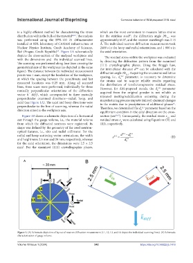
Řež (Prague, Czech Republic) . Figure 1A schematically the axial orientation.
64
depicts the cross-section of the analyzed workpiece and The residual stress within the workpiece was evaluated
with the dimensions and the individual scanned lines. by detecting the diffraction pattern from the examined
The scanning was performed along four lines crossing the {111} crystallographic planes. Using the Bragg’s Law,
geometrical axis of the workpiece (as depicted in the same the inter-planar distance d can be calculated with the
111
figure). The distance between the individual measurement diffraction angle 2ϴ . Acquiring the unconstrained lattice
points was 1 mm, except the borderline of the workpiece, spacing, i.e., d 111 parameter, is necessary to determine
111
at which the spacing between the penultimate and last the strains and to acquire reliable results regarding
0
measured locations was 0.25 mm. Along all scanned the distribution of tensile/compressive residual stress.
lines, three scans were performed, individually for three However, for AM-prepared metals, the d 111 parameter
mutually perpendicular orientations of the diffraction acquired from the original powder is not reliable as
0
vector ⃗ , which corresponded to three mutually repeated melting/solidification occurring during the
perpendicular examined directions—radial, hoop, and manufacturing process imparts (minor) chemical changes
axial (see Figure 1A). The axial and hoop directions were in the matrix due to precipitation of additional phases .
66
perpendicular to the line of scanning, whereas the radial Therefore, we determined the d 111 parameter based on the
direction aimed to the workpiece axis. equilibrium condition in the axial direction on the cross-
0
Figure 1B shows a schematic depiction of a horizontal section (see 16,67 ). Consequently, the residual strain ε and
111
cut through the gauge volume, i.e., the material volume residual stress σ were calculated using Equations (II) and
ij
from which the diffracted neutrons were registered. Its (III), respectively,
shape was defined by the geometry of the used neutron-
optical features, i.e., slits and radial collimator. For the
radial and hoop scattering vector orientations, the width ε 111 = d 111 −d 111 (II)
0
and height were 2.5 mm and 20 mm, respectively, whereas d 111
0
for the axial orientation, the dimensions were 2.5 × 2.5
mm . For the examined {111} crystallographic planes,
2
Figure 1. (A) Schematic depiction of layout of neutron diffraction measurement (L1, L2, L3, and L4 depict the individual scanning lines). (B) Schematic
characterization of gauge volume.
Volume 10 Issue 1 (2024) 342 https://doi.org/10.36922/ijb.1416