
Page 407 - IJB-10-1
P. 407
International Journal of Bioprinting Droplets prepared by air-focused bioprinting
using IVIS Lumina Series III (PerkinElmer), and the governed by three forces, namely F , F , and G, where F S
s
v
bioluminescent signals of each group were analyzed using was the surface tension, F is the viscous force, and G was
v
Living Image Software v.4.7.4. Human IFN-γ and IL-2 the gravity. The surface tension, F = πφγ , tends to hold
A/L
s
released from CAR-T cells in the culture medium were also the inner liquid tip to the nozzle, where φ was the nozzle
harvested and quantified using ELISA kits (MultiSciences). diameter, and γ was the air/liquid interfacial tension; the
A/L
All results were presented as mean ± SD. Comparisons of viscous force, F = 3πηvD, tended to drag the inner liquid
v
two different groups were analyzed using unpaired Student tip off the nozzle, where η was the viscosity of air, v was
t-tests. "ns" denotes no statistical significance. the flow rate of air, and D was the diameter of the inner
liquid tip; the gravity, G = ρ gV, also tended to pull the
3. Results inner liquid tip off the nozzle, where ρ was the density of
L
L
To prepare droplets with controlled shape, co-axial glass- the liquid phase, g was the acceleration of gravity, and V
capillary microfluidic devices were designed and fabricated, was the volume of the liquid tip. Therefore, the design of
where a tapered cylindrical glass capillary was inserted tapered nozzles, which reduced the nozzle diameter and
into a tapered square glass capillary and co-axially aligned, thus the surface tension and introduced focused air flow
as shown in Figure 1a and Figure S1 (Supplementary File). and thus stronger viscous force, was beneficial for the
The liquid phase was infused through the inner channel stable formation of uniform droplets with a smaller size.
while air was blown through the outer channel, both When the viscous force and gravity overcame the surface
of which converge at the end of their nozzles. Droplets tension, i.e., F + G > F , the liquid tip was pulled off the
s
v
were generated by breaking up the liquid phase under the nozzle, forming droplets, as shown in Figure 1a and Figure
focused air flow, and the droplet formation process was S2 (Supplementary File).
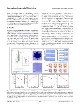
Figure 1. Droplet patterns designed by air-focused microfluidic 3D droplet printing (AFMDP). (a) Schematic diagram of AFMDP, in which surface tension
held the droplet to the nozzle while gravity and viscous drag pulled the droplet off the nozzle. (b) Pattern slicing and (c) droplet printing by AFMDP with a
modified Gcode. Designed pictures were sliced into droplet patterns using a slicing software, and each mesh represents one droplet site. Optical images of
droplets prepared using (d) different air flow rates, (e) different liquid flow rates, and (f) different polymer concentrations. Dependence of droplet diameter
on (g) air flow rate, (h) liquid flow rate, (i) PEG concentration, and (j) alginate concentration. If not specified, the air flow rate was 200 mL/min, and the
liquid flow rate was 10 mL/min.
Volume 10 Issue 1 (2024) 399 https://doi.org/10.36922/ijb.1102