
Page 541 - IJB-10-2
P. 541
International Journal of Bioprinting Bottom-up and top-down VAT photopolimerization
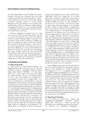
up” bioprinting method. Using the bottom-up principle, patterns using a digital micromirror device (DMD) (DLP®
complex soft tissues can be generated from microscale LightCrafter™ 6500; Texas Instruments). In the DMD
modules as opposed to the top-down approach, which is panel, an array of reflective-coated micromirrors generates
mostly used for the fabrication of conventional scaffolds. light patterns with high resolution (1050 × 920) and speed
Commercial light-based systems are almost entirely (10 kHz switching rate) (Figure 1c). When the bioink is
designed to print hard materials and do not offer multi- introduced into the focal plane of the projected image,
material features, which, in combination with the challenge the digital state of each micromirror can be controlled
of adapting such systems for the use of soft biomaterials as either 0 (dark) or 1 (light reflective), resulting in its
(e.g., hydrogels), has hampered their wide implementation layer-by-layer photocrosslinking. The lateral resolution
in the biofabrication community. of the fabricated object is theoretically limited by the
physical size of the DMD mirrors (7.6 μm); however, the
Therefore, although much progress has been made lateral experimental print resolution was set to 10 μm. A
with the above-mentioned bioprinting systems, they fail stage controller (Thorlabs MTS25-Z8 (MTS25/M-Z8)
to recreate multi-material tissue models with different Motorized Translation Stage) was programmed for vertical
mechanical properties during a single printing session and stage movement, while the UV light source was directed
at relevant clinical printing timeframes. To address this to the DMD panel via an optical path to facilitate light
gap, we have developed a versatile dual-mode bioprinter reflection through the optical lenses onto the stage. For
that can easily be modulated to print in both top-down microfluidics bioprinting, delivery of different bioinks into
and bottom-up approaches. Combining bottom-up and the crosslinking area was achieved using a microfluidics
top-down biofabrication can offer an optimal solution for chip with a polydimethylsiloxane (PDMS) chamber and a
hard–soft multi-materials composites and for bioprinting syringe pump (Figure 1d and f). To thoroughly wash away
tissue–tissue interface models. We have demonstrated the non-crosslinked bioink, we used phosphate-buffered
the possibility for hard–soft multi-material bioprinting in saline (PBS), and the same process was repeated for the
a single construct by generating a musculoskeletal tissue second and the following bioinks. The thickness of the
model. This new system can be implemented to enable the flowing pre-polymer was designed to be around 200 μm.
biofabrication of multi-material microtissues.
Each bioprinting methodology configuration (bottom-up
2. Materials and methods and top-down) needs some specific adjustment, which is
described in sections 3.1 and 3.2, respectively.
2.1. Bioprinting system For microfluidics bioprinting, the delivery of biomaterial
A custom-made DLP multi-material bioprinter was into the crosslinking chamber was regulated by sequential
designed and fabricated as shown in Figure 1a. The DLP injection of the biomaterial in a PDMS microfluidic
bioprinter consists of a digital light projector (Wintech chip designed to act as a crosslinking chamber. The
Digital Light Projector DLP6500), a UV light source microfluidics chamber has diameter of 7 mm. To enhance
(385 nm), UV optical lenses (212 mm focal length), the adhesion of PEGDA-and GelMA-based bioinks on the
and a high-resolution (20 nm) z-axis platform (Figure platform, the bottom glass substrate of the chip was coated
1b and c). The z-axis platform was controlled by a with 3-(trimethoxysilyl)-propyl methacrylate (TMSPMA)
microcontroller (Arduino UNO; Arduino, Italy). A UV Sigma-Aldrich, St. Louis, MO) . Switching from one
[17]
mirror was mounted on a rotating platform to allow for material to another requires washing steps when printing
switching between the bottom-up and top-down printing multi-material structures. Thus, while changing from one
configurations, as shown in Figure 1b. The mirror and DLP material to another, we introduced the DPBS in the culture
were horizontally aligned on the same axis, and rotation of chamber and dipped the model for washing. The bioink
45° in each direction changes the path of the light upward flow is controlled by injecting it into the PDMS chamber
and downward direction in the bioprinter. The bioprinting consecutively. Subsequently, the non-crosslinked material
approach requires positioning of z-axis platform along the was removed by PBS washing, and the bioprinting process
direction of light. For top-down approach, the biomaterial was repeated using a second bioink.
reservoir is lowered, and the mirror is directed, so the
light source is from the top; for bottom-up approach, the 2.2. Reagents and materials
reservoir is lifted, and light source is targeted from the For the bottom-up biofabrication strategy, poly
bottom of reservoir. In these approaches, the UV light is (caprolactone-co-trimethylene carbonate) urethane
projected onto the bioink. The 3D models were designed acrylate (PCT 50:50) (Mw = 3 kDa) was used. The
using AutoCAD, converted to two-dimensional (2D) Photopolymer was synthesized as previously described .
[33]
bitmap slices, and converted to dynamic micromirror For top-down and microfluidics bioprinting, a
Volume 10 Issue 2 (2023) 533 doi: 10.36922/ijb.1017