
Page 546 - IJB-10-2
P. 546
International Journal of Bioprinting Bottom-up and top-down VAT photopolimerization
kPa) can be imitated by tuning the bioink composition compared to control until day 7 after bioprinting (n = 3).
[48]
and crosslinking parameters. However, on day 7, cells grown in monolayer showed a
higher growth rate (n = 3). The viability of encapsulated
3.4. Cell viability and proliferation cells was observed until day 7 in hydrogel post-printing and
The initial results highlight the potential of this quantified. The cell viability in case of both HUVECs and
new bioprinting approach to create multi-material C2C12 until day 7 was more than 89% with no significant
heterogeneous architectures for tissue engineering difference. A slight difference at days 3 and 7 was observed
applications. In addition, the bioprinter can regulate the when compared to gel-free control (n = 3).
structure’s stiffness by controlling printing parameters,
such as hydrogel concentration, PI concentration, and 3.5. Multi-material musculoskeletal model
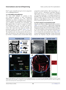
light exposure time. As a proof of concept, cell viability Using the microfluidics configuration described in section 2
and proliferation rate in 5% w/v GelMA was assessed. (Figure 1d), we developed a multi-material bioprinting
Two GelMA-based bioinks, containing HUVECs and approach for generating a musculoskeletal tissue model with
C2C12 cells, respectively, were used, and viability and integrated vasculature. We combined two different cell types,
proliferation assays were analyzed (Figure 3b–e). The i.e., HUVECs and MSCs, for the vasculature, and used C2C12
tests were performed on days 1, 3, and 7 post-printing. cells for the muscle tissue, in the same construct (Figure
The absorbance data were represented as fold increase to 4d). To bioprint the musculoskeletal model (Figure 4a), a
day 0. The absorbance value represented as fold increase co-planar printed pattern depicting a vascular and muscle
for HUVECs in bioprinted system showed similar change structure was bioprinted using the selected biomaterial
Figure 4. Demonstration of multi-material bioprinting musculoskeletal junction. (a) DLP projection pattern showing the bioinks locations. (b) Initial
model made by PEGDA/GelMA. (c) Stacked 3D structure depicting the interface of two bioinks containing HUVECs and C2C12 cells. (d) Bioprinted
muscle and vascular junction comprising three bioinks.
Volume 10 Issue 2 (2023) 538 doi: 10.36922/ijb.1017