
Page 544 - IJB-10-2
P. 544
International Journal of Bioprinting Bottom-up and top-down VAT photopolimerization
The dual-mode DLP system presented in this study projected to fabricate the first layer. For the succeeding
was used for the fabrication of various complex layer, the velocity of stage was increased to move the stage
constructs in order to showcase its potential as a novel in the upward direction, and the new layer was polymerized
biofabrication method. by a dynamic photomask. The supply of pre-polymer
solution was maintained by injecting the polymer into the
3.1. Complex scaffold printing chamber through a microfluidic chip setup. Fabrication
In the proposed bottom-up biofabrication strategy for hard parameters including the depth of pre-polymer stream,
tissue bioprinting (Figure 1a(i)), the desired pattern was curing depth, curing uniformity, and spatial resolution in
created by reflecting UV illumination from the DMD array X, Y, and Z directions were previously optimized for PCT
focused on the specific focal plane to crosslink the pre- using a range of UV exposure times and intensities using
polymer solutions. The light beam was projected from the a stereolithography system . To demonstrate the bottom-
[33]
bottom of the platform to the polymer solution. As the UV up bioprinting approach capability, we engineered 3D
mask was projected, the material stuck to the glass holder scaffolds using PCT (Figure 2a(i) and (ii)).
mounted onto the z-axis platform. The gap between the
glass holder and resin platform defines the layer thickness, The top-down bioprinting mode (Figure 1a(ii)) was
which is maintained by controlling the movement of z-axis used for the fabrication of soft material constructs. The
based on the fabrication stage. During the fabrication printing chamber containing a pre-polymer solution was
of first layer, the stage was lowered to the pre-defined lowered below the adjustable rotational mirror, so the light
height, and as the velocity reached zero, the UV mask was beam was projected from the top of the platform. The glass
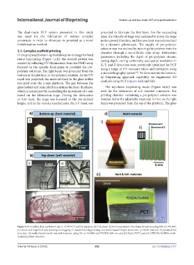
Figure 2. Printability data. (a) Bottom-up: (i, ii) 3D PCT scaffold patterns. (b) Top-down: (i) microvasculature-like shape structures using 60% v/v PEGDA,
(ii) sliced and magnified area showing no clogging of channels during printing, (iii) multichannel shapes structures, (c) Multi-material: (i) pyramid-like
structure, (ii) multichannel multi-material structure using 5% v/v GelMA and PEGDA 60% v/v, and (iii) hard (PCT) and soft (PEGDA-GelMA) multi-
material printed structure.
Volume 10 Issue 2 (2023) 536 doi: 10.36922/ijb.1017