
Page 13 - IJB-3-1
P. 13
Andy Wen Loong Liew and Yilei Zhang
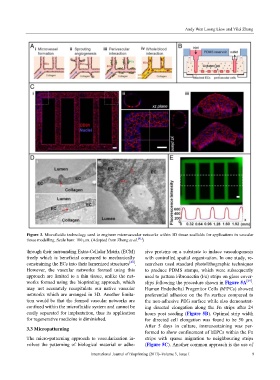
Figure 3. Microfluidic technology used to engineer microvascular networks within 3D tissue scaffolds for applications in vascular
tissue modelling. Scale bars: 100 μm. (Adopted from Zheng et al. [41] )
through their surrounding Extra-Cellular Matrix (ECM) sive proteins on a substrate to induce vasculogenesis
freely which is beneficial compared to mechanically with controlled spatial organization. In one study, re-
constraining the ECs into their lumenized structures [48] . searchers used standard photolithographic techniques
However, the vascular networks formed using this to produce PDMS stamps, which were subsequently
approach are limited to a thin tissue, unlike the net- used to pattern Fibronectin (Fn) strips on glass cover-
works formed using the bioprinting approach, which slips following the procedure shown in Figure 5A [49] .
may not accurately recapitulate our native vascular Human Endothelial Progenitor Cells (hEPCs) showed
networks which are arranged in 3D. Another limita- preferential adhesion on the Fn surface compared to
tion would be that the formed vascular networks are the non-adhesive PEG surface while also demonstrat-
confined within the microfluidic system and cannot be ing directed elongation along the Fn strips after 24
easily separated for implantation, thus its application hours post seeding (Figure 5B). Optimal strip width
for regenerative medicine is diminished. for directed cell elongation was found to be 50 μm.
After 5 days in culture, immunostaining was per-
3.3 Micropatterning
formed to show confinement of hEPCs within the Fn
The micro-patterning approach to vascularization in- strips with sparse migration to neighbouring strips
volves the patterning of biological material or adhe- (Figure 5C). Another common approach is the use of
International Journal of Bioprinting (2017)–Volume 3, Issue 1 9