
Page 226 - IJB-10-3
P. 226
International Journal of Bioprinting Preparation and characterization of branched NGCs
oriented and elongated growth along the direction of connector at each end, and inner bifurcated branches
microchannels after 3 days (Figure S2c–d in Supplementary connecting the two connectors. The two connectors were
File). The calculated PC12 cell orientation angle (θ) configured as hollow straight channels (3 mm in length).
21
in the linear channels was 1.799°, significantly different The branches symmetrically bifurcated from the proximal
from that observed for cells on a flat surface (Figure S2e end and converged at the distal end, forming a loop. Various
in Supplementary File). Moreover, we observed that PC12 DBNs were printed with varying branch angles (0°, 45°, 90°,
cells proliferated rapidly and filled the microchannels on and 120°). Specifically, the branch angle denoted the angle
day 6 (Figure S2f in Supplementary File), although the between the branch channel and the central axis of the
number of proliferated cells within the scaffolds was less connectors. These DBNs were designed for implantation
than those outside the micropatterned scaffolds (Figure to bridge linear nerve gaps. This approach allowed us
S3a–b in Supplementary File). Additionally, PC12 cells to circumvent the impact of selectively regeneration of
within the scaffold displayed directional migration along distinct nerve stumps, thereby enabling a pure assessment
the linear microchannels (Figure S3a in Supplementary of the effect of NGC architectures on nerve regeneration.
File). No significant differences were noted in migration Meanwhile, the MBNs took the form of cuboid scaffolds,
displacement and velocity between cells inside and outside sharing the same dimensions as the DBNs (Figure 1b[ii]).
the scaffold (Figure S3c–d in Supplementary File). These These multi-branched scaffolds featured two straight
results underscored the biocompatibility of the hybrid connectors at both ends, connected to internal triangular
hydrogel, emphasizing the efficacy of its micropatterned structures. In the middle, nine tiny straight channels
structure in guiding cell proliferation, orientation, and converged. The two connectors both measured 3 mm in
migration. Subsequently, the GelMA/PEGDA composite length and 1.3 mm in diameter. The inner tiny straight
prepolymer was further used for the construction of branches were 1.8 mm in length, and their cross-section
branched NGCs. was oval-shaped with a short diameter of 0.5 mm and a
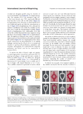
To explore the effect of branch angle and number long diameter of 1.3 mm. The separation distance between
on nerve regeneration, we utilized continuous DLP 3D each tiny branch was 0.3 mm. The number of branches
printing technology to design and fabricate a variety of was designed based on comprehensive considerations,
DBNs and MBNs (Figure 1a). The DBNs were designed including NGC’s inner diameter, volume, and mechanical
as cuboid-like scaffolds (Figure 1b–i), characterized by properties, surpassing the number of natural nerve
dimensions of 12 mm in length, 9 mm in width, and 2.1 branches (e.g., five branches in the facial nerve).
mm in height, with channel diameters set at 1.3 mm. To observe the channels of the branched conduits, a
These scaffolds consisted of a proximal connector, a distal dye solution was injected into the channels. As shown in
Figure 1. Fabrication of branched NGCs. (a) The continuous 3D printing process for branched NGC fabrication. A series of images for varying NGC
designs were imported into the DMD chip, and the prepolymers were crosslinked under exposure to visible light (405 nm). (b) The design of (i) dual-
branched NGCs (45°) and (ii) multi-branched NGCs. (c) The representative photographs of branched NGCs filled with dye (red). Abbreviations: DMD:
digital micromirror device; NGC: nerve guidance conduit.
Volume 10 Issue 3 (2024) 218 doi: 10.36922/ijb.1750