
Page 509 - IJB-10-3
P. 509
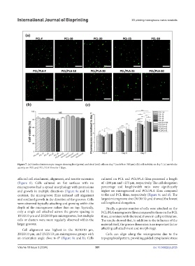
International Journal of Bioprinting                                 3D printing microgroove nerve conduits


            Figure 7. (a) Confocal microscopic images showing live (green) and dead (red) cells on day 7 (scale bar: 300 µm); (b) cell viability on day 7; (c) metabolic
            activity on PCL and PCL/PLA films for 7 days.


            affected cell attachment, alignment, and neurite extension   cultured on PCL and PCL/PLA films possessed a length
            (Figure  8).  Cells  cultured on  flat  surfaces  with no   of ~200 µm and ~275 µm, respectively. The cell elongation
            microgrooves had a spread morphology with protrusions   percentage and length/width ratio were significantly
            and  growth  in  multiple  directions  (Figure  8a  and  b).  In   higher on microgrooved and PCL/PLA films compared
            contrast, the microgroove films induced cell alignment   to flat and PCL films, respectively (Figure 9c and d). The
            and confined growth in the direction of the grooves. Cells   largest microgroove size (30/30/10 µm) showed the lowest
            were observed typically attaching and growing within the   cell length and elongation.
            depth of the microgroove rather than on top. Typically,   Finally, a greater number of cells were attached on the
            only a single cell attached across the groove spacing in   PCL/PLA microgroove films compared to those on the PCL
            10/10/10 µm and 20/20/10 µm microgrooves, but multiple   films, consistent with the trend shown in cell proliferation.
            cells or clusters were more regularly observed within the   The results showed that, in addition to the influence of the
            larger grooves.                                    material itself, the groove dimension is an important factor
               Cell alignment was highest in the 10/10/10 µm,   affecting cell attachment and morphology.
            20/20/10 µm, and 25/25/10 µm microgroove groups with   Cells  can  align  along  the  microgrooves  due  to  the
            an orientation angle close to 0° (Figure 9a and b). Cells   topographical pattern, providing guided cytoplasmic stress

            Volume 10 Issue 3 (2024)                       501                                doi: 10.36922/ijb.2725