
Page 599 - IJB-10-3
P. 599
International Journal of Bioprinting Five-axis printer for hybrid 3D scaffolds
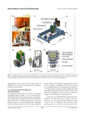
Figure 1. Configuration of the five-axis printer. (a) Photograph of the five-axis printer housed in the safety cabinet. (b) Close-up image of the printing
block. (c) Computer-aided design (CAD) model of the five-axis printer with dimensions labeled with double-headed arrows. (d–f) Detailed CAD view of
the printing block: (d) isometric view; (e) side view; and (f) bottom view. Abbreviation: UV-LED: Ultraviolet light-emitting diode.
systematically structured into three primary steps: (i) G-code. These M-codes facilitate communication between
definition of the use case, (ii) preparation of printing files, the two workflows, enabling the transmission of signals
and (iii) printing strategy. to the printing software and subsequently initiating the
printing process by calling the images. Notably, the on/off
2.4.1. Input parameters for inkjet and command for the inkjet printhead cannot be transmitted
extrusion printing without interrupting the movement of the axis system, and
Inkjet printing employs two-dimensional (2D) bitmaps a trigger is activated before the movement starts.
that digitally apply materials in a non-contact approach.
The printhead path and image processing are decoupled, In this study, Ricoh MH2820 inkjet printheads (native
and no image data is integrated into the G-code. However, resolution: 150 dpi) and a screw extruder (with 0.41
the two processes are connected through the G-code. The mm nozzle tip) were used. The inkjet printing workflow
printing process is initiated through on/off commands is governed by the following input parameters: inkjet
for the printheads, implemented as M-codes within the printing speed (ν ) resolution in printing direction (ϕ),
IJP ,
Volume 10 Issue 3 (2024) 591 doi: 10.36922/ijb.3189