
Page 603 - IJB-10-3
P. 603
International Journal of Bioprinting Five-axis printer for hybrid 3D scaffolds
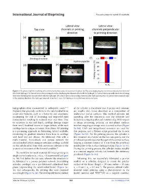
Figure 4. Tri-phasic scaffold consisting of a ceramic hard phase and a bi-material soft phase. (a) Top view displaying the interconnected polymer channels
filled with hydrogel. (b) Lateral view in the printing direction displaying the channels filled with the hydrogel. (c) Lateral view perpendicular to the printing
direction displaying the channels filled with the hydrogel. (d) Lateral view in the printing direction after hydrogel removal. (e) Lateral view perpendicular
to the printing direction after hydrogel removal. Scale bar: 1 mm. (f) Printing accuracy between struts and pore.
topographies often encountered in orthopedic cases. 39-41 of the cylinder is discretized into N points with constant
Implants that precisely conform to the subchondral bone arc lengths (∆s), hence described as a composition of
could offer benefits, such as a better fit and alignment, undistorted partial surfaces. This method prevents ink
minimizing the risk of loosening, and improved joint spreading after the deposition onto the substrate and
biomechanics resulting in reduced wear over time. Due includes a curing step after each rotation of φ. With respect
to variations in size and depth, cartilage damage ranges to image processing, printing on non-planar surfaces
from small, localized lesions to larger defects, while each involves mapping an image onto a curved surface (Figure
cartilage has its unique curvature. Non-planar 3D printing 5a-2iii). CAD and image-based resources are used for
is a promising approach to fabricating hybrid scaffolds, this purpose, and a Python script generated the G-code
mimicking the gradient structure from bone to cartilage (Figure 5a-2iv). For the printing process, the cylinder is
with hard and soft phases. We fabricated PSIs with a first mounted on a holder on the two-axis gantry, and the
multi-material, hierarchical, and porous network for printhead is positioned over the apex of the convex surface,
osteochondral defects using an articular cartilage scaffold keeping a constant distance of 1 mm from the printhead
on the subchondral bone with curvatures relevant to the nozzle plate to the surface during printing (Figure 5a-3v).
anatomical structures of the femoral condyles. During the printing process, the cylinder rotates steadily
42
at a constant angular velocity (ω) beneath the stationary
The workflow for multi-material 3D inkjet printing on
single-curved surfaces (κ = 0; κ > 0) is presented in Figure printhead (Figure 5a-3vi).
1
2
5a. We first define the use case, wherein the structure to Following this, we successfully fabricated a porous
be fabricated is a porous polymer network (resembling scaffold on a cylinder, designed to mimic the patellar
articular cartilage) on a pre-fabricated cylindrical hard surface of the femur (length = 20 mm; radius = 10 mm;
phase (representing the subchondral bone) (Figure 5a- κ = 0 mm ; κ = 0.1 mm ). The process utilized multi-
-1
-1
2
1
1i), and subsequently, the printing files were prepared material inkjet printing using a photopolymer as the
accordingly (Figure 5a-2ii). The developable lateral surface model material and WSS 150 as a support material.
TM
Volume 10 Issue 3 (2024) 595 doi: 10.36922/ijb.3189