
Page 607 - IJB-10-3
P. 607
International Journal of Bioprinting Five-axis printer for hybrid 3D scaffolds
Additionally, inkjet printing offers greater flexibility for rotary movements are commanded as angles and linear
conformal movements over irregular free-form surfaces motions as lengths. The inverse time mode in the G-code,
compared to conventional 3D printing technologies. With widely used in four and five-axis applications, was found to
inkjet technology being a non-contact method, operating prevent jerky movements when synchronizing linear and
at a distance of 1 mm and a typical droplet speed ranging rotation. In the subsequent step, the generated G-code can
from 4 to 8 m/s, the inkjet printhead can navigate irregular be imported into Mach3.
surfaces with more freedom, unlike FFF, and the need for Finally, the printing strategy is initiated by mounting
strict conformal movement can be partly eliminated. the implant on the two-axis gantry using the handling
This is followed by the preparation of the printing files element (Figure 6a-3vii). The printing process starts with
(Figure 6a-2iii and 2iv). Working with free-form surfaces material deposition on the nasal surface, followed by a
presents unique challenges in generating printable files curing process. The printhead and the UV-LED move at a
compared to single-curved surfaces. Taking into account defined z height of approximately 5 mm, while the palatal
the aforementioned physical limitations of the printing implant rotates beneath the printing block during the
block, creating an equivalent image for mapping 2D images printing process.
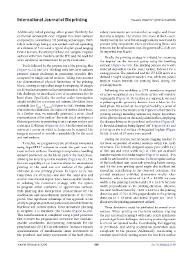
on 3D surfaces requires surface approximation. To address Following this workflow, a GTR membrane-inspired
this challenge, we introduced a set of requirements for the structure was printed on a free-form surface with variable
hard phase. Specifically, the surface under investigation topography (Figure 6). To validate our approach, we used
should exhibit low curvature and minimal deviation from a patient-specific geometry derived from a fetus for the
a straight line (l path ~ l projected ) (Figure 6a-2iii). Meeting these hard phase. We scaled up the original model by a factor of
requirements minimizes the impact of surface distortions. seven to enhance the visual clarity. Figure 6b illustrates the
In a further step, we manually generated a point cloud printing strategy including various key stages: deposition
representation of the surface. The point cloud undergoes a of the photopolymer on the nasal palatal surface, displaying
flattening process by projecting it onto a planar surface and the distance between the printhead and surface (Figure 6b-
creating a 2D bitmap (Figure 6a-2iv). The flattened surface i); the palatal implant being flipped 180° (Figure 6b-ii); and
serves as a canvas on which an image can be mapped. The printing on the oral surface of the palatal implant (Figure
image is mirrored to provide a printable file for the nasal 6b-iii). A total of 10 layers were printed.
and oral surfaces.
During the process, partial nozzle clogging resulted in
Thereafter, we programmed the printhead movement the local connection of certain sections within the mesh
using hyperMILL® software to create the path over the structures. The initially designed square pore width (w )
p
nasal and oral surfaces. The design incorporates a handling of 800 µm and strut width (w ) of 1500 µm exhibited
s
element positioned on the lateral part of the hard phase, transformations to circular shapes (Figure 6c and d). This
allowing for mounting on the machine (Figure 6a-2v). The could be attributed to two reasons: (i) the irregular surface
five-axis capability of our machine allows for automatized of the hard phase may cause ink spreading before curing,
printing on the nasal and oral surfaces of the palatal and (ii) the slow printing speed might also facilitate ink
obturator in one printing process. In Figure 6a-2v, two spreading, contributing to the observed outcomes. The
trajectories are extracted—one over the nasal area and printed structures exhibited dimensions smaller than
another over the oral region. Users have complete freedom intended, with a deviation of -16.15 ± 18.18% for pore
in selecting the movement strategy, with the option width in the printing direction and 1.8 ± 23.37% for pore
to program either conformal or approximate surfaces. width perpendicular to the printing direction. Likewise,
Path planning also incorporates considerations for the the strut width deviated by -18.05 ± 6.61% in the printing
acceleration and deacceleration movements of the CNC direction and -27.79 ± 8.79% perpendicular to the printing
portal. One significant advantage of our approach is the direction (n = 10 struts and pores) (Figure 6e). Table 3
ability to program printhead paths independently from the illustrates the printing parameters utilized.
hardware and control system. Once movement planning These deviations could be attributed to several error
is complete, it is translated into G-code (Figure 6a-2vi). sources. When printing on free-form surfaces, aligning
This transformation is completed using a post-processor the part and synchronizing it with multi-nozzle printheads
that converts the programmed movement into machine- present significant challenges. Achieving precise alignment
specific coordinates, incorporating commands for the is crucial for optimal results. Coordinating the triggering
printhead and UV-LED on/off controls. To ensure smooth of printheads and setting acceleration parameters adds
synchronization of simultaneous linear movements of complexity to the process. Additionally, maintaining a
the printhead and rotary movements of the hard phase, constant speed while moving across the free-form surface
Volume 10 Issue 3 (2024) 599 doi: 10.36922/ijb.3189