
Page 600 - IJB-10-3
P. 600
International Journal of Bioprinting Five-axis printer for hybrid 3D scaffolds
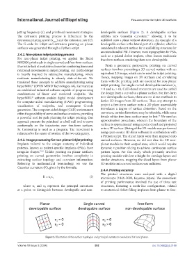
jetting frequency (ƒ), and printhead movement strategies. developable surfaces (Figure 2). A developable surface
The extrusion printing process is influenced by the exhibits zero Gaussian curvature, allowing it to be
37
extrusion printing speed (ν EXT ) and the extrusion rate (C). unfolded onto a plane without distortion. An example of a
The G-code for inkjet and extrusion printing on planar developable surface is the lateral part of a cylinder, which is
surfaces was generated through a Python script. considered a relevant surface for a scaffolding structure for
an osteochondral PSI. However, most topographies for PSIs,
2.4.2. Non-planar inkjet printing process such as a palatal defect implant, often feature multiscale
For non-planar inkjet printing, we applied the Ricoh free-form surfaces, rendering them non-developable.
MH2820 printheads to single-curved and free-form surfaces.
Due to the lack of available software for combining linear and From a geometric perspective, printing on curved
rotational movements in inkjet printing, our methodology surfaces involves presenting a 3D curved surface with an
is heavily inspired by subtractive manufacturing, where equivalent 2D image, which can be used for inkjet printing.
multiaxis manufacturing is already state-of-the-art. We Hence, mapping images on 3D surfaces and correlating
translated these concepts to additive manufacturing using them with the printing path are essential for non-planar
hyperMILL® (OPEN MIND Technologies AG, Germany) as inkjet printing. For single-curved developable surfaces (κ₁
an established industrial software capable of programming = 0 and κ₂ > 0), CAD-based resources are used to unfold
combinations of linear and rotational toolpaths. The the design from a curved to a planar surface. For free-form
hyperMILL® software enables digital model development non-developable surfaces, there are no direct methods to
for computer-aided manufacturing (CAM) programming, derive 2D images from 3D surfaces. Thus, any attempt to
visualization of toolpaths, and consequent G-code project a free-form surface onto a 2D plane unavoidably
generation. The computer-aided design (CAD) environment introduces a degree of surface distortion. Based on the
offers the possibility of curve and surface creations, providing curvature, certain distortions may be tolerable, while some
38
a powerful tool for path planning for inkjet printing. Our details of the free-form surface may be lost. We used an
approach presents the printhead as a ball mill tool to move approximation procedure, wherein the boundary of the
conformally on the trajectories over free-form surfaces. surface is approximated using a point cloud and projected
5x Contouring is used as a program. The movement is onto a 2D surface. Slicing of the 3D models was performed
referenced to the center of rotation of the two-axis gantry. using open-source 3D slicer software in combination with
a Python script. The sliced layers were then mapped onto
2.4.3. Image processing for non-planar inkjet printing curved surfaces. However, we did not slice the 3D non-
Implants tailored to the unique anatomy of individual planar models in their warped state, which would require
patients, known as patient-specific implants (PSIs), have dynamic z-position slicing to achieve continuous surface
irregular shapes. 35,36 Unlike printing on planar surfaces, pattern layers. For this study, which primarily involves
printing on curved geometries involves complexity in printing models with low z-height for cartilage layers and
extracting surface topology and curvature information. similar structures, mapping the sliced layers from planar
Referring to mathematical terminology, we use the 3D models onto curved surfaces was sufficient.
Gaussian curvature (K), given by the formula:
2.4.4. Printing accuracy
The printed structures were analyzed with a digital
K = κ κ (I) microscope (VHX-5000, Keyence, Japan). The assessment
1 2
of printing performance involved the use of three test
where κ₁ and κ₂ represent the principal curvatures structures, featuring a mesh-like configuration, related
at a point, to distinguish between developable and non- to anatomical defect-filling implants from planar to free-
Figure 2. Illustration of the surface topologies and principal curvatures considered for hard phases.
Volume 10 Issue 3 (2024) 592 doi: 10.36922/ijb.3189