
Page 81 - IJB-4-2
P. 81
Shuai C et al.
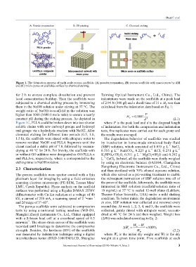
A. Powder preparation B. 3D printing C. Chemical etching
Figure 1. The fabrication process of multi-scale porous scaffolds. (A) powder preparation, (B) porous scaffolds with macro pores by AM
and (C) micro pores on scaffolds surface by chemical etching.
for 2 h to ensure complete dissolution and prevent Taiming Optical Instrument Co., Ltd., China). The
local concentration buildup. Then the scaffolds were indentations were made on the scaffolds at a peak load
subjected to a chemical etching process by immersing of 2.94 N (300 gf) and a dwell time of 15 s. H was then
V
them in the NaOH solution under stirring at 37 °C. The calculated from the indentation data based on Eq. 1:
weight ratio of NaOH-to-scaffold in the solution was
higher than 1000 (1600:1 mole ratio) to ensure a nearly
constant pH during the etching process. As depicted in (2.1)
Figure 1C, PLLA could be broken down into two shorter where P is the peak load and d is the diagonal length
soluble chains with new carboxyl groups and hydroxyl of indentation. For both the compression and indentation
end groups via a hydrolysis reaction with NaOH. After tests, five replicates were carried out for each group and
chemical etching for different time periods (0.5, 1.0, the results were averaged.
1.5 h), the scaffolds were rinsed with ultrapure water to The degradation behavior of scaffolds was studied
remove residual NaOH and PLLA fragments until the by incubation in home-made simulated body fluid
eluant reached a stable pH of 7.0, followed by vacuum- (SBF) solution, which consisted of 8.035 g L NaCl,
−1
drying at 40 °C for 24 h. For brevity, the scaffolds with 0.355 g L NaHCO , 0.225 g L KCl, 0.231 g L
−1
−1
−1
3
or without GO addition were designated as GO/PLLA-x K HPO •3H O, 0.311 g L MgCl •6H O and 0.292 g
−1
2
2
2
2
4
and PLLA-x, respectively, where x corresponded to the L CaCl . In brief, all the scaffolds were firstly weighed
−1
2
etching time in NaOH solution. by using an electronic balance (FA1004, Changzhou
Hengzheng Electronic Instrument Co., Ltd., China)
2.3 Characterization and then sterilized with 70% ethanol aqueous solution,
The porous scaffolds were sputter coated with a thin which also served as a pre-wetting treatment to enable
platinum layer for imaging by using a field emission the subsequent permeation of SBF solution into all of
scanning electron microscope (FE-SEM, Tescan Mira/ the pores of the scaffolds. Afterwards, the scaffolds were
LMU, Czech Republic). Phase analysis on the scaffold immersed in SBF solution (scaffold/solution ratio of
surfaces was performed using a Rigaku D/MAX 2550V 10 mg/mL) at 37 °C in sealed 12-well plates (LabServ,
diffractometer with Cu-Kα radiation at a voltage of 40 Thermo Fisher Scientific, USA) under a mild shaking
kV, a current of 250 mA, a scanning speed of 2 °•min –1 condition. To better mimic the degradation environment
and 2θ range of 5°~65°. in vivo, SBF solution was collected and renewed every
The porous scaffolds were subjected to compression second day. At week 1, 2, 3, 4, and 5, the scaffolds were
tests by using a universal testing machine (WD-D1, collected, gently rinsed with ultrapure water, vacuum-
Shanghai Zhuoji instruments Co., Ltd., China) equipped dried at 40 °C for 24 h and then weighed. Weight loss
with a S-beam load cell at a crosshead speed of 0.5 (ΔWt) was calculated according to Eq. 2:
mm•min . The stress-strain curves of the scaffolds were
–1
recorded until breakage to determine the compressive
strength. Besides, the hardness (HV) of the scaffolds (2.2)
was measured by indentation technique using a digital where W is the initial dry weight and Wt is the dry
0
microhardness tester (HXD-1000TM/LCD, Shanghai weight at a given time point. Five scaffolds at each
International Journal of Bioprinting (2018)–Volume 4, Issue 2 3