
Page 527 - IJB-10-4
P. 527
International Journal of Bioprinting 3D printed substrate for adhesion tests
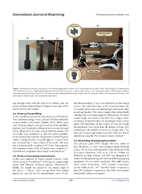
Figure 1. Development and post-processing of 3D-printed polypropylene probes. (a) 3D probe design in Autodesk Fusion 360 software. (b) Polypropylene
(PP) 3D-printed probe (c) Industrial standard stainless steel (SS) probe used in probe tack testing of the transdermal system (TDS) products and (d)
Automated post-processing setup for the 3D-printed probe featuring different setup components, including the robotic arm and probe mounted on the
probe mount. Abbreviation: LSS: Lynxmotion smart servo.
was brought down with the help of the robotic arm; the and diiodomethane (3 μL) were deposited on the sample
probe was then rotated using the stepper motor against the surface. The entire procedure of the drop placement onto
sander for post-processing. the sample surface was recorded using an automated video
recording function. The contact angles were automatically
2.4. Probe surface profiling calculated for each image using the ellipse fitting. The mean
Surface profile measurements of post-processed PP probes contact angle was based on the final drop images, where
were conducted using a Veeco Dektak 150 diamond probe
contact surface profilometer (Bruker, USA). Before each the droplet remained stable and unchanged (static contact
angle) after deposition on the surface. At least six to eight
scan, PP probe samples were placed on the surface profiler’s measurements were taken from the images of static drop
platform, and the analytical diamond probe was positioned
at the null position to make contact with the sample. The remaining on the samples to derive the average value. The
PP probes were positioned so that the surface profiler’s obtained contact angle values were then fitted into the SE
29
probe started scanning from the periphery of the PP probe calculation using the Wu (harmonic mean) method.
surface. During the test, the probe applied 10 mg of force 2.6. 3D printing of polypropylene plates
and traversed the 7 mm surface of the probe. The scan Peel adhesion plates (PAP) (length: 200 mm; width: 50
was conducted with a resolution of 10 µm. Subsequently, mm; thickness: 1.2 mm) were designed using Autodesk
the roughness values of the PP probes were compared to Fusion 360 software and imported to the MethodX FDM
reported skin roughness values found in the literature. 28 3D printer (Makerbot, USA) as an STL file. Within the
2.5. Probe surface energy measurement MethodX printing software, the PAP was adequately fit
Probes were analyzed by Future Digital Scientific Corp. within the virtual printing area with the following printing
(USA) using the DropMeter A290 optical contact angle parameters: 0.2 mm print resolution, 50% infill density,
TM
meter with Windows 10-based software (TrueDrop ). 210°C nozzle temperature, 114°C chamber temperature
TM
Briefly, the sample was placed on the sample stage of (at the build plane), 70°C chamber heater temperature,
the device; a 500-μL micro syringe filled with testing and 130°C platform temperature. The PAPs were printed
liquid was used for the SE measurement; water (5 μL) horizontally without any support.
Volume 10 Issue 4 (2024) 519 doi: 10.36922/ijb.3735