
Page 73 - IJB-5-2
P. 73
Zhang Y
the printhead to achieve more sophisticated extrusion- inlets, the same printhead could print cell-laden solid
based 3D-printing. Microfluidics is skilled at combining hydrogel fiber, cell-laden hollow hydrogel fiber, and
multiple flows from separate inlets into a single stream. hollow double-layered hydrogel fiber. Leng et al. took a
Due to the low Reynolds number, materials stay in separate step further and developed a programmable multi-inlet
laminar layers in a single microfluidic channel; hence, microfluidic printhead . The seven inlets for bioinks
[61]
different materials can be printed in close proximity. were individually controlled by solenoid valves. A base
Colosi et al. fabricated a simple two-inlet microfluidic biopolymer was introduced into the printhead from a
chip as the printhead (Figure 4A and B) . Two separate separate channel and extruded continuously from a wide
[50]
bioinks were introduced into the microfluidic chip nozzle, forming a polymer ribbon that served as a substrate
from the two inlets and combined into a single stream. on which the bioinks were deposited. The opening and
Although extruded as a single hydrogel fiber, the two closing periods of the solenoid valves determined the
bioinks stay separate. A similar two-channel design was extrusion length of the bioink from each of the seven
demonstrated by Hardin et al. By adjusting the flow rate nozzles thus the patterns printed with the bioinks on the
[59]
at the two inlets, seamless switching between different base biopolymer substrate. Using this approach, authors
materials during printing was accomplished. Wei et al. were able to print hydrogel sheets with well-controlled
demonstrated a multi-inlet microfluidic printhead . pores.
[60]
Cells, hydrogel precursors, sacrificial material, and water Microfluidics is capable of keeping different bioinks
were introduced into the microfluidic chip from separate in separate layers; even they are in close proximity.
inlets. These materials were hydrodynamically focused Nonetheless, in certain scenarios, it is desirable to
into a single outlet channel and extruded from the nozzle blend multiple materials to create a multicomponent
for bioprinting. By adjusting the relative flow rate at the but homogeneous bioink. Fortunately, the mixing in
A B
C D
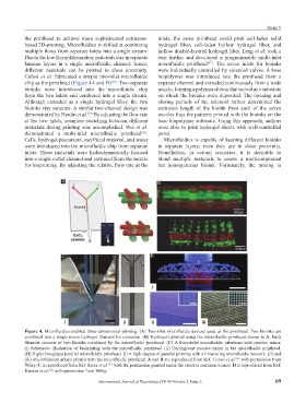
Figure 4. Microfluidics-enabled three-dimensional-printing. (A) Two-inlet microfluidic devices used as the printhead. Two bioinks are
combined into a single micro hydrogel filament for extrusion. (B) Hydrogels printed using the microfluidic printhead shown in A. Each
filament consists of two bioinks combined by the microfluidic printhead. (C) A three-inlet microfluidic printhead with passive mixer.
(i) Schematic illustration of bioprinting with the microfluidic printhead. (ii) Herringbone passive mixer in the microfluidic printhead.
(D) High-throughput parallel microfluidic printhead. (i) A high-degree of parallel printing with a bifurcating microfluidic network. (ii) and
(iii) Microfilament arrays printed with the microfluidic printhead. A and B are reproduced from Ref. Colosi et al. with permission from
[50]
Wiley. C is reproduced from Ref. Serex et al. with the permission granted under the creative common license. D is reproduced from Ref.
[51]
Hansen et al. with permission from Wiley.
[52]
International Journal of Bioprinting (2019)–Volume 5, Issue 2 69