Page 269 - IJB-10-5
P. 269

International Journal of Bioprinting                                A TPMS framework for complete dentures


                    cx,y,z) =−0.064 ⋅  x +  y + 0.9           Table 2. Expression of gradient porous-structure function
                     (
                                       2
                                           2
                                                       (X)                            Function
                   
                       (
                                          2
                               30.143
                     tx,y,z) =−       ⋅  x +  y 2              Type          c(x,y,z)           t(x,y,z)
                   
               The derivation methods for  c(x,y,z) and  t(x,y,z)   A-I  –0.064 .  x +  y  + 0.9  3 – 0.143 .  x +  y 2
                                                                                   2
                                                                                2
                                                                                                      2
            of  the  other  eight  structures  are analogous,  and  their
            corresponding outcomes are presented in  Table 2.   A-II    –0.064 .  x +  y  + 0.9  2 + 0.143 .  x +  y 2
                                                                                2
                                                                                   2
                                                                                                      2
            Substituting the expressions c(x,y,z) and t(x,y,z) for each
                                                                                   2
                                                                                2
            structure into Equation VII yields the model expression.  A-III  –0.064 .  x +  y  + 0.9  2.5
               Nine gradient porous models were modeled in      B-I     0.064 .  x +  y  + 0.45  3 – 0.143 .  x +  y 2
                                                                                  2
                                                                                                      2
                                                                               2
            MSLattice (Oraib Al-Ketan, UAE).  This software offers
                                        39
            flexibility, enabling users to design their own TPMS lattice   B-II  0.064 .  x +  y  + 0.45  2 + 0.143 .  x +  y 2
                                                                                                      2
                                                                               2
                                                                                  2
            based on level-set approximations. The modeling principle
            involves offsetting the level-set approximation equation   B-III  0.064 .  x +  y  + 0.45  2.5
                                                                               2
                                                                                  2
            used to define the isosurface, followed by constructing
            a solid domain at spatial nodes enclosed between two   C-I         0.68          3 – 0.143 .  x +  y 2
                                                                                                      2
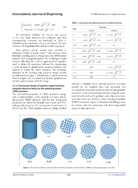
            surfaces  to  obtain  the  lattice  structure.  The  schematic
            diagrams of the resulting nine gradient change models   C-II       0.68          2 + 0.143 .  x +  y 2
                                                                                                      2
            are illustrated in Figure 4. Additionally, it can be observed
            from the figure that the transitions between gradients are   C-III  0.68              2.5
            uniform and consistent with the design.
                                                               outlined in  Section  2.1.2., optimal gradient structures
            2.1.3. Framework design of implant-supported fixed   suitable for the required sizes were generated. The
            complete dentures based on the optimal gradient    structural type remained consistent, with the same gradient
            TPMS structure                                     variations in unit size and relative density. Using the center
            The mechanical properties of TPMS structures change
            with a radial gradient, unlike uniform structures. Firstly,   point of each tooth as the gradient center, these structures
            the gradient TPMS structure with the best mechanical   were then filled into IFCDs to create functional gradient
            properties was identified through experiments and FEA.   TPMS frameworks. Figure 5A illustrates the filling process
            Subsequently, based on the dimensions of each tooth in   for molars, with the remaining teeth filled sequentially
            IFCDs and the TPMS gradient structure design method   using the same approach.


                     Figure 4. The overall schematic and top views of the three-periodic minimal surface (TPMS)-based gradient porous models.


            Volume 10 Issue 5 (2024)                       261                                doi: 10.36922/ijb.3453
   264   265   266   267   268   269   270   271   272   273   274