
Page 73 - IJB-6-1
P. 73
Lee, et al.
BioSeg
File Processing
STL G-code Conventional
File Processing
File STL G-code
Segmentation STL G-code Compilation
.
.
.
CAD Model Bioprinting
STL G-code Compilation
Figure 2. Process flow for file preparation for bioprinting, comparing between the two different file
processing methods.
rate of dissolution, providing sufficient time before A B
secondary cross-linking through ultraviolet (UV)
cross-linking of GelMA.
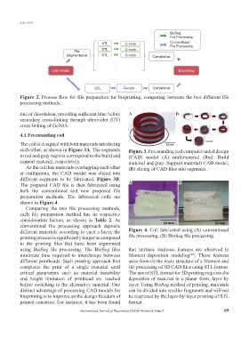
4.1 Freestanding coil
The coil is designed with both materials interlacing
each other, as shown in Figure 3A. The segments Figure 3. Freestanding coil computer-aided design
in red and gray regions correspond to the build and (CAD) model (A) multimaterial (Red: Build
support material, respectively. material and gray: Support material) CAD model,
As the coil has materials overlapping each other (B) slicing of CAD files into segments.
at multipoints, the CAD model was sliced into
different segments to be fabricated, Figure 3B.
The prepared CAD file is then fabricated using A B
both the conventional and new proposed file
preparation methods. The fabricated coils are
shown in Figure 4.
Comparing the two file processing methods,
each file preparation method has its respective
consideration factors, as shown in Table 2. As
conventional file processing approach deposits
different materials according to each z-layer, the Figure 4. Coil fabricated using (A) conventional
printing process is significantly longer as compared file processing, (B) BioSeg file processing.
to the printing files that have been segmented
using BioSeg file processing. The BioSeg files that intrinsic staircase features are observed in
minimize time required to interchange between filament deposition modeling . These features
[45]
different printheads. Such printing approach first arise from (i) the basic structure of a filament and
completes the print of a single material until (ii) processing of 3D CAD files using STL format.
critical parameters such as material instability The use of STL format for 3D printing requires the
and height limitation of printhead are reached deposition of material in a planar form, layer by
before switching to the alternative material. One layer. Using BioSeg method of printing, materials
distinct advantage of processing CAD models for can be divided into smaller fragments and will not
bioprinting is to improve on the design freedom of be restricted by the layer-by-layer printing of STL
printed construct. For instance, it has been found format.
International Journal of Bioprinting (2020)–Volume 6, Issue 1 69