
Page 90 - IJB-6-2
P. 90
3D-printed borate glass scaffolds for bone repair
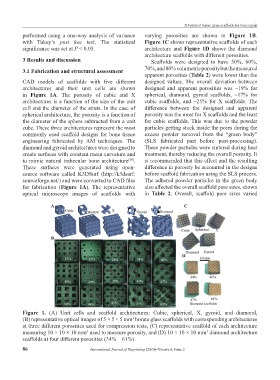
performed using a one-way analysis of variance varying porosities are shown in Figure 1B.
with Tukey’s post hoc test. The statistical Figure 1C shows representative scaffolds of each
significance was set at P < 0.05. architecture and Figure 1D shows the diamond
architecture scaffolds with different porosities.
3 Results and discussion Scaffolds were designed to have 50%, 60%,
3.1 Fabrication and structural assessment 70%, and 80% volumetric porosity but the measured
apparent porosities (Table 2) were lower than the
CAD models of scaffolds with five different designed values. The overall deviation between
architectures and their unit cells are shown designed and apparent porosities was ~19% for
in Figure 1A. The porosity of cubic and X spherical, diamond, gyroid scaffolds, ~17% for
architectures is a function of the size of the unit cubic scaffolds, and ~25% for X scaffolds. The
cell and the diameter of the struts. In the case of difference between the designed and apparent
spherical architecture, the porosity is a function of porosity was the most for X scaffolds and the least
the diameter of the sphere subtracted from a unit for cubic scaffolds. This was due to the powder
cube. These three architectures represent the most particles getting stuck inside the pores during the
commonly used scaffold designs for bone tissue excess powder removal from the “green body”
engineering fabricated by AM techniques. The (SLS fabricated part before post-processing).
diamond and gyroid architectures were designed to These powder particles were sintered during heat
create surfaces with constant mean curvature and treatment, thereby reducing the overall porosity. It
to mimic natural trabecular bone architecture . is recommended that this effect and the resulting
[38]
These surfaces were generated using open- difference in porosity be accounted in the designs
source software called K3DSurf (http://k3dsurf. before scaffold fabrication using the SLS process.
sourceforge.net/) and were converted to CAD files The adhered powder particles in the green body
for fabrication (Figure 1A). The representative also affected the overall scaffold pore sizes, shown
optical microscope images of scaffolds with in Table 2. Overall, scaffold pore sizes varied
A C
B
D
Figure 1. (A) Unit cells and scaffold architectures: Cubic, spherical, X, gyroid, and diamond,
(B) representative optical images of 5 × 5 × 5 mm borate glass scaffolds with corresponding architectures
3
at three different porosities used for compression tests, (C) representative scaffold of each architecture
measuring 10 × 10 × 10 mm used to measure porosity, and (D) 10 × 10 × 10 mm diamond architecture
3
3
scaffolds at four different porosities (34% – 61%).
86 International Journal of Bioprinting (2020)–Volume 6, Issue 2