
Page 102 - IJB-6-4
P. 102
Triple-layered coaxial nozzle for 3D bioprinting
cyanoacrylate solution and sodium bicarbonate was conceived as a non-Newtonian fluid and its physical
employed to adhere the different components into parameters, such as density and dynamic viscosity,
a single structure (Figure 1A). From a transverse were used as input for calibrating the models. Air
view, the coaxial nozzle comprised three walls, was, however, conceived as a Newtonian fluid and
two rings, and one cylinder, with Gauges (G) its density and dynamic viscosity were also provided
ranging from 13 to 25 G. This configuration led to as input for the simulations. A parametric analysis
three different flow channels, namely, channel a, was performed by varying the inlet pressure (P) of
b, and c, as shown in Figure 1B. channel b between 10 and 70 kPa and the Gauge of
Based on this prototype, a computationally this flow channel was fixed at 18 G. Outlet velocity
aided design model of the three flow channels was and pressure were studied at the outlet of the flow
developed and studied using computational fluid channel and compared to previously reported
dynamics simulations in COMSOL Multiphysics literature to validate the design in terms of cell
®
software. A two-dimensional axisymmetric domain viability.
of flow channel b and a glass printing surface, with Three different coaxial nozzles were designed
a 100 µm air interface in between, was modeled and varying the area of the middle channel (namely, b
simulated based on the overall design of the coaxial in Figure 1B) and subsequently 3D printed using
nozzle. This channel was of special interest as the biocompatible photopolymer resins, namely, dental
nozzle is intended for the extrusion of single-layered SG FLSGOR01 and dental LT clear (Figure 1C).
tubular structures and the cell-laden hydrogel will The dimensions of each channel are reported in
be extruded through this channel. The hydrogel was Table 1, along with the area of flow channel b (used
A B C
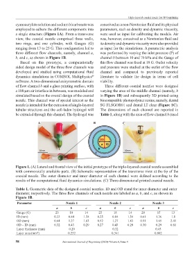
Figure 1. (A) Lateral and frontal view of the initial prototype of the triple-layered coaxial nozzle assembled
with commercially available parts. (B) Schematic representation of the transverse view at the tip of the
coaxial nozzle. The outer diameter and inner diameter of each channel were defined according to the
results of the computational fluid dynamics simulations. (C) Three-dimensional printed coaxial nozzle.
Table 1. Geometric data of the designed coaxial nozzles. ID and OD stand for inner diameter and outer
diameter, respectively. The three flow channels of each nozzle are labeled as a, b, and c, as shown in
Figure 1B.
Parameter Nozzle 1 Nozzle 2 Nozzle 3
a b c a b c a b c
Gauge (G) 23 18 14 25 18 14 20 15 13
ID (mm) 0.33 0.84 1.54 0.25 0.84 1.54 0.61 1.36 1.8
OD (mm) 0.64 1.27 1.83 0.52 1.27 1.83 0.91 1.65 2.41
OD – ID (mm) 0.32 0.43 0.29 0.27 0.43 0.29 0.30 0.29 0.61
Layer thickness (mm) 0.20 0.32 0.45
Layer area (mm ) 0.232 0.341 0.802
2
98 International Journal of Bioprinting (2020)–Volume 6, Issue 4