
Page 104 - IJB-6-4
P. 104
Triple-layered coaxial nozzle for 3D bioprinting
2.4 Cell culture and embedding 2.5 Bioprinting of tubular structures
Before bioprinting experiments, human bone For bioprinting, the coaxial nozzles were
osteosarcoma cells MG-63 (ATCC CRL-1427™) submerged in 70% (v/v) ethanol for 1 h before
®
were cultured in complete growth medium experiments and subsequently washed with sterile
consisting of Dulbecco’s Modified Eagle Medium 1 × PBS in a biosafety cabinet. The modified
supplemented with 10% (v/v) fetal bovine 3D printer was thoroughly wiped with 70%
serum and 1% (v/v) Penicillin-Streptomycin (v/v) ethanol and exposed to UV germicidal light
(10,000 U/ml) and maintained in a CO incubator for 1 h inside a biosafety cabinet.
2
at 37°C. Upon the culture reached a confluence of Each nozzle comprised three flow channels
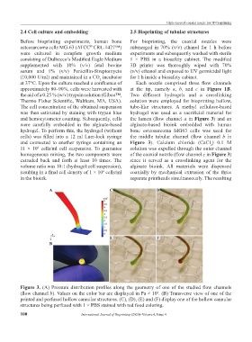
approximately 80–90%, cells were harvested with at the tip, namely a, b, and c in Figure 1B.
the aid of a 0.25 % (w/v) trypsin solution (Gibco™, Two different hydrogels and a crosslinking
Thermo Fisher Scientific, Waltham, MA, USA). solution were employed for bioprinting hollow,
The cell concentration of the obtained suspension tube-like structures. A methyl cellulose-based
was then estimated by staining with trypan blue hydrogel was used as a sacrificial material for
and hemocytometer counting. Subsequently, cells the lumen (flow channel a in Figure 3) and an
were carefully embedded in the alginate-based alginate-based bioink embedded with human
hydrogel. To perform this, the hydrogel (without bone osteosarcoma MG63 cells was used for
cells) was filled into a 12 ml Luer-lock syringe the middle tubular channel (flow channel b in
and connected to another syringe containing an Figure 3). Calcium chloride (CaCl ) 0.1 M
2
11 × 10 cells/ml cell suspension. To guarantee solution was expelled through the outer channel
6
homogeneous mixing, the two components were of the coaxial nozzle (flow channel c in Figure 3)
extruded back and forth at least 10 times. The since it served as a crosslinking agent for the
volume ratio was 10:1 (hydrogel:cell suspension), alginate bioink. All materials were dispensed
resulting in a final cell density of 1 × 10 cells/ml coaxially by mechanical extrusion of the three
6
in the bioink. separate printheads simultaneously. The resulting
A C D
E F
B
Figure 3. (A) Pressure distribution profiles along the geometry of one of the studied flow channels
(flow channel b). Values on the color bar are displayed in Pa × 10 . (B) Transverse view of one of the
4
printed and perfused hollow cannular structures. (C), (D), (E) and (F) display one of the hollow cannular
structures being perfused with 1 × PBS stained with red food coloring.
100 International Journal of Bioprinting (2020)–Volume 6, Issue 4