
Page 235 - IJB-10-6
P. 235
International Journal of Bioprinting DIW of concave hydroxyapatite scaffolds
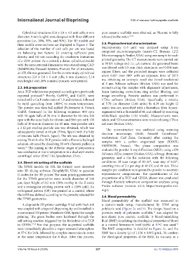
Cylindrical structures (2.8 × 2.8 × 4.2-unit cells; 6 mm pure ceramic scaffolds were obtained, as Pluronic is fully
diameter; 9 mm height) were designed with three different released in the water. 37,38
porosities (i.e., 20%, 35%, and 50%). The 3D models and
their middle cross-sections are displayed in Figure 1. The 2.5. Physicochemical characterization
selection of the number of unit cells per cm was based Macroporosity (>3 µm) was analyzed using X-ray
on balancing two factors: (i) ensuring sufficient pore computed microtomography (micro-CT, Skyscan 1272
density, and (ii) not exceeding the resolution limitations Microtomograph; Bruker, USA) using one sample for each
of a DIW printer. As a control, a dense cylindrical model printed geometry. The CT measurements were carried out
with the same external dimensions was created using CAD at 90 kV voltage and 111 µA current; the generated beam
(SolidWorks; Dassault Systems, France). For all structures, was filtered with 0.5-mm-thick aluminum and 0.038-mm
an STL file was generated. For the in vitro study, cylindrical copper filters; and the projected images were collected
structures (2.8 × 2.8 × 1-unit cells; 6 mm diameter; 2.14 every 0.02º over 180º with an exposure time of 3375
mm height) with 20% nominal porosity were printed. ms, obtaining an isotropic voxel size (voxel resolution)
of 3 µm. NRecon software (Bruker, USA) was used for
2.3. Ink preparation reconstructing the samples with alignment adjustments,
An α-TCP solution was prepared according to a previously beam hardening corrections, ring artifact filtering, and
reported protocol. Briefly, CaHPO and CaCO were image smoothing. Porosity analysis was performed in
52
3
4
mixed with a Ca:P molar ratio of 1.5 and sintered, followed CTAn software (Bruker, USA). Specifically, a volume
by rapid quenching from 1400ºC to room temperature. of 5.70 cm diameter (2.66 units) by 4.29 cm height (2
The powder was then ball-milled (Pulverisette 6; Fritsch units) was cut, smoothed with a Kuwahara filter, binary-
GmbB, Germany) in the following sequence: 450 rpm segmented with a threshold of 40, and refined by removing
with 10 agate balls of 30 mm in diameter for 40 min; 500 white/black speckles (<30 voxels). Measurements were
rpm with the same balls for 60 min; and 500 rpm with 100 taken, and 3D reconstructions were rendered using CTvox
balls of 10 mm in diameter for 60 min. Fine powder with software (Bruker, USA).
a 3.12 µm median particle size was obtained, which was The microstructure was analyzed using scanning
subsequently sieved at 40 µm (Filtra, Spain) with the help electron microscopy (SEM; Neon40 Crossbeam™
of zirconia balls (Tosoh, Japan). The ink was obtained by workstation; Carl Zeiss, Germany) after coating the
mixing 70 wt.% of α-TCP powder with a Pluronic hydrogel samples with a carbon evaporated layer (K950X;
solution, obtained by dissolving 30 wt% Pluronic pellets in EMITECH, France). The phase composition was
water. The mixing in the different stages of preparation evaluated by powder X-ray diffraction (XRD), using a D8
37
was conducted at room temperature in a dual asymmetric Advance diffractometer (Bruker, USA), a Bragg–Brentano
centrifugal mixer (DAC 150; Speedmixer, USA).
geometry, and a Cu Kα radiation with the following
2.4. Direct ink writing of the scaffolds conditions: 2θ scan range of 20–50°, scan step of 0.02°,
The TPMS models (in STL file format) were imported counting time of 2 s per step at 40 kV, and 40 mA. Three
into 3D slicing software (Simplify3D, USA) to generate samples per condition were ground to powder to ascertain
G-codes for the 3D printer. The main printing parameters representative compositions. The quantification of the
for the TPMS geometries were: nozzle diameter of 250 proportions of α-TCP and CDHA phases was conducted
µm; layer height of 0.2 mm (20% overlap in the Z-axis); through Rietveld refinement composition analyses using
and a rectangular printing pattern with a 100% infill. An Profex software (version 4.0.3; https://www.profex-xrd.
orthogonal pattern (OP) was printed as a control, where org/).
the infill was defined according to the porosity selected for 2.6. Blood permeability
the TPMS geometries.
Blood permeability of the scaffold was measured in
A disposable 3D printer cartridge filled with fresh ink a custom-made setup, manufactured by FDM using
was coupled with a tapered dispensing tip and installed in polylactic acid (Figure 2a and b). The design, based on a
a customized 3D printer (Fundació CIM, Spain) for sample previous study of polymeric scaffolds, was adapted for
19
printing. The green bodies were hardened through the non-elastic pure ceramic scaffolds. A blood-mimicking
self-setting reaction triggered by the hydrolysis of α-TCP fluid (BMF) simulating the rheological properties of blood
53
to CDHA. 37,38 For that purpose, the as-printed scaffolds at a normal hematocrit level (46%) at 37ºC was used.
were immediately placed in a vapor-saturated atmosphere The BMF composition is detailed in Figure 2c, and the
at 37ºC for 24 h, followed by complete immersion in water BMF has a density (ρ) of 1.126 ± 0.002 g/mL. To confirm
at the same temperature for 6 days. After this process, the rheological properties of the BMF, its viscosity as a
Volume 10 Issue 6 (2024) 227 doi: 10.36922/ijb.3805