
Page 154 - IJB-7-4
P. 154
3D Printer for Anatomic Models
3. In the third test, a 50% downscaled version of a simulate a situation of printing hard plastic support
human bladder was printed based on a 3D model under a silicone structure (Figure 7A).
segmented from a computed tomography (CT) image 5. In the fifth test, the same model was used as in the
earlier. To test the feasibility of such a large internal fourth test, but now the PLA was printed on top of
cavity with overhanging areas, no support was used the silicone to simulate laying the filament as an
inside. The envelope dimensions of this downscaled inclusion into the silicone matrix (Figure 7B).
bladder were approximately 35 × 30 × 25 mm, and 6. The sixth test was planned to give some synthesis of
the wall thickness was changing between 1.5 and the features investigated through the previous tests.
2 mm (Figure 6). The ribcage and the surrounding soft tissues were
4. The fourth test involved a pair 15 × 15 × 3 mm square segmented from the CT image of a newborn using
silicone and PLA multi-material chips on top of each 3D-Slicer, and the model was printed (Figure 8).
other. The silicone was printed on top of the PLA to The ribs and the support structures were printed from
PLA and the surrounding soft tissue was printed
A B from silicone. To mimic bone structure, the ribs were
printed with a 30% gyroid infill, while 80% infill was
used for the soft tissue.
3. Results
All test objects were successfully printed. The thin-walled
shell of the first test (Figure 4) did not collapse during or
after printing, despite having only 0.7 mm wall thickness.
The 40% gyroid block of the second test (Figure 5)
was cut in half with a blade after crosslinking to reveal
the internal structure (Figure 5C).
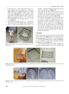
Figure 4. Thin-walled silicone rubber shell during (A) and after The downscaled bladder in the third test (Figure 6)
printing (B). had minor material integrity errors at the top due to the
A B C
Figure 5. Silicone block with 40% volume fraction gyroid infill during (A) and after printing (B), and after slicing with a blade (C) to reveal
the internal structure.
A B C
Figure 6. A downscaled human bladder with no internal support during (A) and after printing (B), and after slicing with a blade (C) to reveal
the internal cavity.
150 International Journal of Bioprinting (2021)–Volume 7, Issue 4