
Page 153 - IJB-7-4
P. 153
Jaksa, et al.
define a multi-material printhead and generate G-codes poly-lactic acid (PLA) filament from Fillamentum
for multi-material FFF-DIW print jobs. No post- Manufacturing (Hulín, Czech Republic) was used with the
processing of the generated G-code files is necessary, and E3D V6 FFF printhead in case of prints that demonstrate
an extrusion correction factor can also be set to fine-tune the multi-material capabilities. PLA was chosen as it is an
dosing accuracy, when necessary. To start a print job, the easily accessible and popular FFF material.
generated G-code files must be uploaded to the Duet 2 2.4. Printing tests
Wi-Fi board through the Duet Web Interface. This way,
the printer is likely also compatible with other popular For accurate dosing, the silicone printhead was calibrated
slicing software, such as Cura or Simplify3D. for the chosen material using a KERN PES 42002M
scale (Kern & Sohn GmbH, Balingen, Germany). After
2.3. Materials this, 15 × 15 × 10 mm silicone blocks were printed with
The selected silicone material is a high-viscosity single- various speeds and layer thicknesses to find reasonable
component condensation-crosslinking liquid silicone settings for further printing tests. The integrity of the
rubber called Elkem AMSil 20101 (Elkem Silicones, printed cubes was qualitatively evaluated by observing
them and then slicing them with a blade to see if there are
Oslo, Norway), which was used with the Viscotec DIW any internal faults (Figure 3).
printhead. This material is intended for cold extrusion; Based on the calibration prints, a printing speed of
therefore, no heating or other means of energy input is 15 mm/s and a layer thickness of 0.3 mm were chosen
required during printing. Moreover, a 1.75 mm diameter for further trials. Furthermore, every printed object
was left on the building platform untouched for 24 h to
ensure sufficient crosslinking before any manipulation
or inspection. After calibration, the system’s ability to
print silicone objects with closed internal cavities, infill
structuring and thin walls as well as to combine silicone
DIW and thermoplastic FFF was assessed by conducting
six printing tests:
1. In the first test, a thin-walled shell was printed based
on the same 15 × 15 × 10 mm cuboid that was used
for the calibrations. In this case, only two lines of
outer contour were used, resulting in approximately
0.7 mm shell wall thickness (Figure 4). This is
relevant to anatomic models in case of printing
vessels or membranes, which feature thin walls.
2. The second test involved a silicone block of the same
dimensions as in the first test, but with 40% volume
fraction gyroid infill structuring to simulate down-
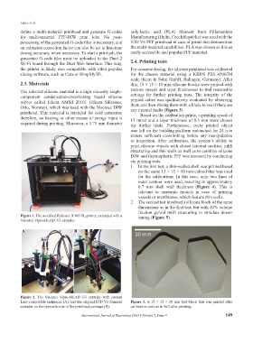
Figure 1. The modified Railcore II 300 ZL printer, extended with a tuning (Figure 5).
Viscotec Vipro-HEAD 3/3 extruder.
A B
Figure 2. The Viscotec Vipro-HEAD 3/3 extruder with custom
Luer-compatible endpieces (A), and the original E3D V6 filament Figure 3. A 15 × 15 × 10 mm test block that was printed after
extruder on the opposite side of the printhead carriage (B). calibration and cut in half after printing.
International Journal of Bioprinting (2021)–Volume 7, Issue 4 149