
Page 156 - IJB-8-1
P. 156
Design Criteria for Patient-Specific Mandibular Implant
used to filter the influence of a certain feature size with a j j
maximum or minimum value (Table 3). Z sd . j ave wherej AB BB , CB T (2)
,
,
,
j
L
L
n 9 Z ( j Z)
SDZ j 1 100. (3)
n ( 1)
Where, sd value is one of the nine segmental bone
length, width, and height dimensions.
The worst mandible structure case, that is, the
structural weakest case can be filtered through calculating
the V and SDZ values. The mandible with the largest V
value and SDZ value definition <1.0 was the worst case,
and their corresponding values were 13.71 and 0.66,
respectively (Table 3).
2.2. Design criteria for reconstructed implant
with large defect segment
Solid models of A, B, and C regions according to the
definitions in Table 1 were constructed and divided in
the CAD system (Creo Parametric v2.0, PTC, Needham,
MA, USA) based on the previously selected worst
mandible structure. Large mandible defects including
single segment C and B and combined A+B segment were
defined and designed with corresponding reconstructed
implants according to the following five design points:
(i) The thickness of the implant shell was set to 0.5 mm;
(ii) the height of the implant was designed to be 1/2 of
the height of the bone segment, and the bone graft space
for postoperative prosthesis is reserved at the top for
subsequent follow-up; (iii) the thickness of the implant
M 1 3 was designed to be 2/3 of the bone segment thickness to
M=F×LB; HB ; I TB HB* allow space for the flap, vascular pedicle, and soft tissue
2
to pass through; (iv) the implant needs to be designed
I 64
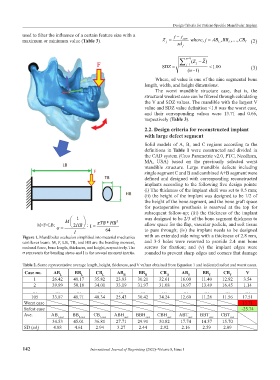
Figure 1. Mandibular occlusion simplified into material mechanics with an extended side wing with a thickness of 2.8 mm,
cantilever beam. M, F, LB, TB, and HB are the bending moment, and 3-5 holes were reserved to provide 2.4 mm bone
occlusal force, bone length, thickness, and height, respectively. The screws for fixation; and (v) the implant edges were
σ represents the bending stress and I is the second moment inertia. rounded to prevent sharp edges and corners that damage
Table 2. Some representative average length, height, thickness, and V values obtained from Equation 1 and indicated safest and worst cases.
Case no. AB L BB L CB L AB H BB H CB H AB T BB T CB T V
1 26.42 48.17 35.82 23.83 30.21 32.61 16.00 11.40 12.92 3.54
2 39.99 50.18 34.01 33.19 31.97 31.08 16.97 13.49 16.45 1.14
… … … … … … … … … … …
105 33.87 48.71 40.34 25.43 30.42 34.24 12.60 11.28 11.56 17.51
Worst case 13.71
Safest case -25.74
Ave. AB L.ave BB L.ave CB L.ave ABH .ave BBH .ave CBH .ave ABT .ave BBT .ave CBT .ave
34.53 45.01 36.81 27.71 29.91 30.82 17.74 14.57 15.70
SD (sd ) 4.88 4.61 2.94 3.27 2.44 2.92 2.16 2.59 2.09
j
142 International Journal of Bioprinting (2022)–Volume 8, Issue 1