Page 157 - IJB-8-1
P. 157

Lin, et al.
           Table 3. Top five worst cases and corresponding Z  and SD values.
                                               j
            Top five worst cases  V  Z ABL  Z BBL  Z CBL  Z ABH  Z BBH  Z CBH  Z ABT  Z BBT  Z CBT  SDZ  SDZ≤1.0
                                                                                              value
                    1          17.51 −0.13  0.80  1.20  0.70  −0.21 −1.17  2.38  1.27  1.98   1.06      X
                    2          15.43  0.48  −0.32 −1.02  2.21  0.96  0.26  1.99  0.10  1.27   1.00      X
                    3          13.71 −0.44  1.16  1.78  0.14  0.79  −0.08 −0.02  0.58  0.79   0.66      O
                                                                                                    (worst case)
                    4          12.31  0.15  0.72  0.88  1.21  −0.29 −0.32  0.39  0.31  0.82   0.49      O
                    5          12.14  0.62  0.58  1.04  0.66  1.54   0.25  0.06  −0.15 −1.41  0.78      O

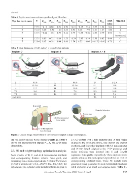
           Table 4. Main dimensions of C, B, and A + B reconstructed implants.
            Implant C                        Implant B                          Implant A + B


              L               43.0              L               46.0              D               Ø 2.6
              D              Ø 2.6              D               Ø 2.6             H1              18.0
              H               17.7              H               19.0              H2              15.0
             T1               8.4              T1                7.6              H3              34.0
             T2               2.8              T2                2.8              T1              7.6
           Unit: mm                                                               T2              2.8


                             Bone graftff
                             Bone graft
                                                                                   Extended side wing
                                                                         Round edge
                                                                         Round edge
                                               1 1/2 of the segmental/2 of the se
                                                  bone height
                                                  bone he
                                      Flap tissue

                                  2/3 of the segmental
                                  2/3 of the segmental
                                       hi k
                                    b bone thickness
           Figure 2. Clinical design consideration of a reconstructed implant in large defect segment.
           the soft tissues such as blood vessels (Figure 2). Table 4   a CAD system with 3 mm diameter and 15 mm length
           shows the reconstruction implant C, B, and A+B main   aligned to the left/right canine, side incisor and incisor
           dimensions.                                         positions, and four other implants with 4.5 mm diameter
                                                               and  14  mm  length  aligned  to  the  1 /2   premolar  and
                                                                                                 nd
                                                                                              st
           2.3. FE and weight topology optimization analysis   molar  positions  were  inserted  into  C  and  B/A+B
           Solid models of B, C, and A+B reconstructed implants   segmental bone grafts, respectively. These implants were
           and  corresponding  fixation  screws,  bone  graft,  and   used to simulate the post-operative prosthesis to receive
           remaining bones were exported into ANSYS Workbench   corresponding  occlusal  loads.  Three  FE  models  were
           (ANSYS Workbench v18.2, ANSYS Inc., PA, USA) for    generated using quadratic 10-node tetrahedral structural
           simulation. Six-cylinder solid dental implants deigned in   solid elements after mesh convergence tests (Table 5).

                                       International Journal of Bioprinting (2022)–Volume 8, Issue 1       143
   152   153   154   155   156   157   158   159   160   161   162