
Page 33 - IJB-8-1
P. 33
Tian, et al.
Trajectories from the lateral view (i.e., the yz-plane that of the human finger by a large margin. On the
in Figure 2) of the 6 designs are reported in Figure 10. contrary, all our five designs are more flexible and can
We observed that the flexion of the baseline (Design 5) better replicate the human finger. We notice that designs
was limited as its minimum y coordinate was larger than 2 and 6 had the similar deformation curves; therefore,
Table 3. Comparison of the joint connectors in various robotic hand designs
Connector Type Maximum restoring force Force transmission
Fishing line Ligament 0 1 Bowden cable for flexion and extension
Crocheted ligament Ligament 0 1 cable for flexion and 1 cable for extension
Solid pin Hinge 0 1 cable for flexion and 1 cable for extension
Flexible pin Hinge 0 1 cable for flexion and 1 cable for extension
Rubber band (this design) Ligament 1.5 N with 2 mm rubber band 1 cable for flexion, extension achieved via the
restoring force
Rubber band (this design) Ligament 3.1 N with 4 mm rubber band 1 cable for flexion, extension achieved via the
restoring force
Table 4. Ablation study on the finger design
Design Cable link method Joint connector Pulley solution Maximum force DIP ROM
1 Through hole and knot 4 mm rubber band 2 holes through phalanx 18.973N [0 , 95 ]
o
o
(2 mm beneath the surface of
phalanx)
2 Through hole and knot 4 mm rubber band 2 holes through phalanx 8.652N [0 , 90 ]
o
o
(3 mm beneath the surface of
phalanx)
3 DIP attaching knot 2 mm rubber band 2 holes through phalanx 10.301N [0 , 90 ]
o
o
(1 mm beneath the surface of
phalanx)
4 DIP attaching knot 2 mm rubber band 1 hole through phalanx 23.348N [0 , 100 ]
o
o
(1 mm beneath the surface of
phalanx) 2 nylon string windings
5 Inside knot Pin joint Hollow body 3.345N [0 , 70 ]
o
o
6 Through hole and knot 4 mm rubber band 4 nylon string windings 19.306N [0 , 100 ]
o
o
Maximum forces are measured from fingertip (in N), and ranges of motion are measured by the rotation angle of DIP (in degree).
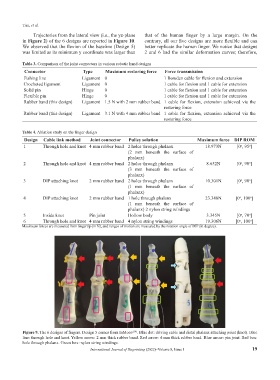
Figure 9. The 6 designs of fingers. Design 5 comes from InMoov . Blue dot: driving cable and distal phalanx attaching point (knot). Blue
[39]
line: through hole and knot. Yellow arrow: 2 mm thick rubber band. Red arrow: 4 mm thick rubber band. Blue arrow: pin joint. Red box:
hole through phalanx. Green box: nylon string windings.
International Journal of Bioprinting (2022)–Volume 8, Issue 1 19