
Page 172 - IJB-8-4
P. 172
Metal 3DP Hybrid Suture Anchor for Osteoporosis
were prepared by Sawbones (Sawbones; Pacific Research (0°) to the block surface. Then, the block was clamped
Laboratories, Vashon, WA) (Figure 3) [17-19] . and mounted in a parallel position on an ElectroPulsTM
To compare the effectiveness of the failure strength E3000 testing machine (Instron Corp., Norwood, MA)
of the HSA with wing mechanism, 40 HSAs were prepared with Bluehill2 software for 0.1 s sampling rate (Version
and each 20 HSAs was arranged for 7.5pcf and 20pcf bone 2.26, Instron Corp., Norwood, MA) pullout tests. The
blocks. Each bone type was divided into two groups with suture loops of the anchor were secured between the
and without the wing open. A total of 20 commercial solid anchor and hook, leaving a constant gage of 10 cm
anchors (CSAs; CorkScrew FTII, Arthex Inc. Naples, FL, between the hook and block surface (Figure 3). A 10 N
USA) of the same diameter and length were also prepared preload was applied to each specimen and then a test load
as the control group for comparing failure strength with 12.5 mm/s was applied parallel to the axis of anchor
(Figure 2B). These three types of anchors were termed insertion for the osteoporotic trabecular bone.
HSAWW, HSAWOW, and CSA for hybrid anchor with For dynamic testing, a 0.5-Hz sinusoidal cyclic
the wing open, hybrid anchor without the wing open, and loading profile of 15 – 150 N for 300 cycles after a
commercial anchor, respectively. Subsequent subgroups preload of 10 N was applied. Each sample was pulled
were divided into two groups from these two groups, five to failure at a constant extension rate of 12.5 mm/s after
of which were for static and after dynamic load pullout cyclic loading to determine failure strength. Whether it
experiments (Table 1, which shows the group arrangement). was static test or dynamic test after 300 cyclic loading,
Each suture anchor was inserted into a failure strength and failure mode were observed,
20 mm × 20 mm × 40 mm, Sawbone block, perpendicular including anchor pullout or suture breakage. The
A B
C D E F
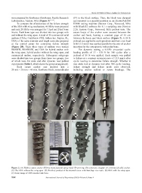
Figure 2. (A) Hybrid suture anchor (HSA)s manufactured using metal 3D printing. (B) schematic diagram of commercial solid anchor.
(C) The HSA without the wing open. (D) Finished product of the internal screw with front/top view scale. (E) HSA with the wing open.
(F) X-ray image of HSA inserted into bone.
164 International Journal of Bioprinting (2022)–Volume 8, Issue 4