
Page 183 - IJB-9-1
P. 183
International Journal of Bioprinting PEEK skull implant in cranioplasty
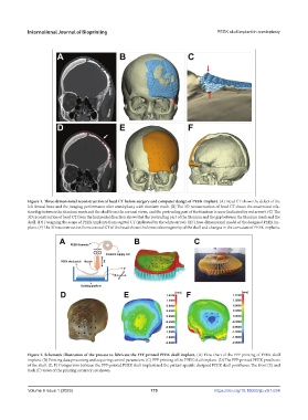
Figure 1. Three-dimensional reconstruction of head CT before surgery and computer design of PEEK implant. (A) Head CT shows the defect of the
left frontal bone and the imaging performance after cranioplasty with titanium mesh. (B) The 3D reconstruction of head CT shows the anatomical rela-
tionship between the titanium mesh and the skull from the coronal views, and the protruding part of the titanium is seen (indicated by red arrow). (C) The
3D reconstruction of head CT from the horizontal direction shows that the protruding part of the titanium and the gap between the titanium mesh and the
skull. (D) Designing the scope of PEEK implants from sagittal CT (indicated by the white arrow). (E) Three-dimensional model of the designed PEEK im-
plant. (F) The 3D reconstruction from coronal CT of the head shows thickness inhomogeneity of the skull and changes in the curvature of PEEK implants.
Figure 2. Schematic illustration of the process to fabricate the FFF-printed PEEK skull implant. (A) Flow chart of the FFF printing of PEEK skull
implant. (B) Printing data processing and acquiring control parameters. (C) FFF printing of the PEEK skull implant. (D) The FFF-printed PEEK prosthesis
of the skull. (E, F) Comparison between the FFF-printed PEEK skull implant and the patient-specific designed PEEK skull prostheses. The front (E) and
back (F) views of the printing accuracy are shown.
V
Volume 9 Issue 1 (2023)olume 9 Issue 1 (2023) 175 https://doi.org/10.18063/ijb.v9i1.634