
Page 100 - IJB-9-2
P. 100
International Journal of Bioprinting Holistic charge-based MEW scaffold model
A
B C D E
F
G H I J
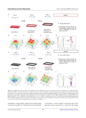
Figure 3. Exemplification of three charge effects (global, local and polarization effect) in two modes. (A) and (F) schematize the equivalent physical
scenarios for Mode 1 (B–D) and Mode 2 (G–I), respectively. Phase 1 in (A) schematizes a positively charged segment approaching a positively charged
plate. Phase 2 in (A) schematizes a positively charged segment approaching a positively charged grid. Phase 3 in (A) schematizes a charged segment with
polarization approaching a charge grid with polarization. (B) can be understood in a similar way. The dimensionless parameters enabling Mode 1 and
Mode 2 include α = 3, β = 3 (for Mode 1) or 0.1(for Mode 2), ξ = 15, η = 1, and K = 1. Black curves in (B–D, G–I) denote the locations on the energy surface
prescribed by the toolpath or briefly prescribed locations. (E) and (J) show the evolution of black curves in these two modes with z. As explained later, these
curves are essentially the lateral characteristic curves for Mode 1 and Mode 2.
noted that an energy surface represents the lateral energy process since z is kept constant. Considering that the jet
variation at a specific time instant during the jet deposition deposition process proceeds as z decreases, the energy
Volume 9 Issue 2 (2022) 92 https://doi.org/10.18063/ijb.v9i2.656