
Page 101 - IJB-9-2
P. 101
International Journal of Bioprinting Holistic charge-based MEW scaffold model
surfaces evolving with z are always displayed together, interfiber distance ξ and the normalized polarization
thereby constituting a series of surface representations (or distance η, respectively. Specifically, an increment in ξ and
a mode of energy surface evolution) that depict a complete η helps to increase the observability of the local effect and
jet deposition process. the polarization effect, respectively. Since ξ is relatively
large (e.g., ξ = 15 in Figure 3) in Mode 1 and 2, the pore
3.2.1. Energy surface evolution representation structure is “seen” earlier by the incoming jet segment than
It is now clear that each jet deposition process corresponds the charge polarization of the structure. The equivalent
to a specific mode of energy surface evolution. physical scenario can be described as a uniformly charged
A concomitant question that arises herein is how many segment that is now approaching a uniformly charged
modes can be observed under different conditions typified grid (Phase 2 in Figure 3A and F). The local effect due to
by the previously defined dimensionless parameters. the porous structure results in an additional topological
To answer this question, it is helpful to fundamentally change to the energy surface, which assumes an overall
understand the way in which the topology of the energy concave (Mode 1) or convex (Mode 2) surface with some
surface is affected by parameters involved in the model. local “ridges” (black lines in Figure 3C and magenta dashed
These effects, namely, charge effects, are found to assume curve in Figure 3E) or “grooves” (black lines in Figure 3H
three forms, including the global effect, local effect, and and magenta dashed curve in Figure 3J), respectively, at
polarization effect. Specifically, the global effect is defined prescribed locations.
as the global energy variation (increase or decrease) from As the deposition process further proceeds (i.e., z
the center to the periphery of the scaffold. Next, the local approximating unity), the charge polarization of the porous
effect is defined as the local energy variation (increase or structure is eventually “seen” by the incoming jet segment,
decrease) from the locations prescribed by the toolpath and the equivalent physical scenario is schematized in
(shortened as prescribed locations in later contents) to Phase 3 in Figure 3A and 3F, whereby the polarization
their adjacent pores. Finally, the polarization effect is effect is additionally considered. Correspondingly, an
defined as the local energy decrease caused by the charge additional topological change to the energy surface caused
polarization within the incoming jet segment and the by this polarization effect is observed represented by
scaffold at prescribed locations. some significant narrow “grooves” at prescribed locations
To get a better understanding of these three effects, two (Figure 3D, magenta curve in Figure 3E and I, magenta
modes, namely, Mode 1 and Mode 2, will be explained solid curve in Figure 3J).
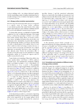
in detail herein. The dimensionless parameters enabling 3.2.2. Formulation and evaluation of different modes
Mode 1 and Mode 2 include α = 3, β = 3 (for Mode 1) or of energy surface evolution
0.1 (for Mode 2), ξ = 15, η = 1, and K = 1. The equivalent
physical scenarios corresponding to Mode 1 and Mode 2 are It should be noted that in Mode 1, wherein the scaffold is
schematized in Figure 3A and F, respectively. In addition, positively charged, the topological changes in the energy
the corresponding energy surface evolution is shown in surface caused by the local effect and polarization effect as
Figure 3B–D and 3G–I, respectively. At the initial phase illustrated in Phase 3 (Figure 3A) are antagonistic (i.e., at
(Phase 1) of the deposition process, since the incoming jet the prescribed locations as indicated by the black lines, the
segment is considered far-field from the deposited fibers local effect results in “ridges” while the polarization effect
(i.e., z is large), the charge polarization in the incoming results in grooves”) and thus are differentiable. However,
jet segment is negligible. Moreover, the incoming jet in Mode 2, wherein the scaffold is negatively charged and
segment is unable to “see” the porous structure. This for a typical range of ξ and η, the topological changes in the
equivalent physical scenario can be depicted as a uniform energy surface profile caused by the local and polarization
positive charge segment approaching a uniform positively effects are synergistic (i.e., both result in local “grooves” at
or negatively charged plate (Phase 1 in Figure 3A and F), prescribed locations), which makes them indifferentiable.
and therefore, the global effect is the singular effect in Based on the analysis in Figure 3, depending on the
action. This singular global effect is reflected by a strictly polarity of the net charges in the scaffold and their effect on
concave (for Mode 1) or convex (for Mode 2) parabola the topology of the energy surface, there are two types of
(Figure 3B and 3G) on the energy surface. global effects (⊕/⊖) and local effects (⊕/⊖), respectively.
As the deposition proceeds (i.e., z decreases), depending Specifically, the global effect (⊕) results in a relatively high-
on the dimensionless parameters, the local and polarization energy state at the center of the scaffold compared to the
effect arises sequentially on the energy surface, which periphery, while the global effect (⊖) results in a relatively
are observed to be primarily affected by the normalized low-energy state at the center of the scaffold compared to
Volume 9 Issue 2 (2022) 93 https://doi.org/10.18063/ijb.v9i2.656