
Page 130 - IJB-9-2
P. 130
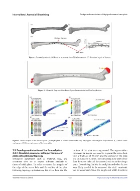
International Journal of Bioprinting                     Design and manufacture of high-performance bone plate


                          Figure 2. Femoral prosthesis. (A) Reverse reconstruction. (B) Substantiation. (C) Simulated repair of fracture.


                                 Figure 3. Schematic diagram of the femoral prosthesis restraint and load application.


            Figure 4. Stress analysis of the femoral plate. (A) Nephogram of overall displacement. (B) Nephogram of bone plate displacement. (C) Overall stress
            nephogram. (D) Stress nephogram of the bone plate.


            3.3. Topology optimization of the femoral plate    contour  of  the  plate  were  segmented.  The  segmentation
            3.3.1. Simulated parameter setting of the femoral   command in Inspire was used to segment the screw hole
            plate with optimized topology                      with a thickness of 0.8 mm and the contour of the plate
            Simulation parameters such as material, load, and   to a thickness of 0.2 mm. The remaining plate part (other
            constraint were set in Inspire software similarly to   than the screw hole and the contour) was set as the design
            those of solid plates. In order to ensure the integrity of   space. Considering that the femoral plate and other factors
            the edge of the screw hole and the outline of the plate   were likely needed to be removed, the draft  constraint
            following topology optimization, the screw hole and the   was set downward. Since the length and width directions


            Volume 9 Issue 2 (2023)                        122                      https://doi.org/10.18063/ijb.v9i2.658