
Page 129 - IJB-9-2
P. 129
International Journal of Bioprinting Design and manufacture of high-performance bone plate
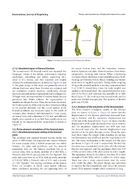
Figure 1. Reverse reconstruction of the femoral prosthesis.
3.1.2. Simulated repair of femoral fracture the screw, friction force, and the interaction between
The reconstructed 3D femoral model was imported into muscle, ligament, and plate. These forces have three forms:
Geomagic Design X for further optimization (clipping, compression, bending, and torsion. When compressing
subdivision, smoothing, and holistic repatching, etc.), the femoral head, the femur would naturally produce both,
saved in STL format, and then imported into Inspire bending and torsional forces; hence, bending and torsion
software for substantialization, as shown in Figure 2A and need not to be applied separately. Taking adults weighing
B. The plate design in this study was primarily aimed at 70 kg as the research subjects, a one-leg compression load
oblique fractures, since these fractures are common and F of 2,100 N (about three times the body weight) was
are considered unstable fractures; additionally, oblique applied to the femoral head. The contact between the other
fractures can easily induce displacement and are dangerous. end of the femur and meniscus was partially set as fully
To begin with, we imported the 3D-substantiated femoral fixed (Figure 3). The mesh type was a mixed mesh, and the
prosthesis into Rhino software for segmentation to mesh was divided automatically. The number of divided
simulate an oblique fracture. Then, the incision was closed, grids was 471,296.
the fixation position of the plate was determined according
to the fracture direction, and the curved surface of the 3.2.2. Analysis of the simulation of the femoral plate
femoral prosthesis was extracted based on the width of The finite element simulation results of the femoral
common plate, deviated, and thickened by 3 mm. Lastly, plate are shown in Figure 4. Figure 4A shows that the
six round holes with a diameter of 3.52 mm and different displacement of the femoral prosthesis decreased from
depths were opened on it, so that there would not be any top to bottom, and the maximum displacement was
threads in the simulation holes temporarily, as shown in 13.06 mm at the femoral head. Figure 4B shows that the
Figure 2C. displacement of the plate decreased from top to bottom,
and the maximum displacement was 4.09 mm near
3.2. Finite element simulation of the femoral plate the femoral head after the femoral displacement was
3.2.1. Simulated parameter setting of the femoral transferred to the plate through screws. When the plate
plate bore three times the weight while standing on one leg,
The simulated and repaired femoral fracture model was the deformation was small and met the requirements for
saved in STP format and imported into Inspire software use. The stress nephograms of the sample and the plate
for stress analysis. First, a bolted connection was added are shown in Figure 4C and D, respectively. We find that
between the plate and prosthesis, and the material the stress was concentrated on the plate after the femoral
parameters were set. The femoral prosthesis was set as fracture was repaired, and the maximum stress was 3.90
cortical bone, with an elastic modulus of 17.00e MPa, a e MPa on both sides of the plate across its entire length.
2
3
Poisson’s ratio of 0.30, and a density of 1.23e kg/mm . The The maximum stress of the plate is less than TC4 yield
-6
3
plate and screw were set as TC4, with an elastic modulus strength of 8.60e MPa, which is within the safety range.
2
of 116.52e MPa, a Poisson’s ratio of 0.31, and a density There was also a stress concentration near the screw
3
of 1.92e kg/mm . The loading conditions of the human hole inside the plate. The plate’s design was optimized
-6
3
femur are complex, in which many factors influence to improve the biocompatibility and reduce the femoral
those conditions, including the pre-tightening force of plate’s (TC4 material) weight, which measured 15.24 g.
Volume 9 Issue 2 (2023) 121 https://doi.org/10.18063/ijb.v9i2.658