
Page 420 - IJB-9-3
P. 420
International Journal of Bioprinting 3DP PILF cage for osteoporotic
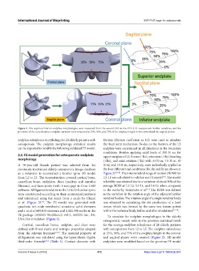
Figure 1. The superior/inferior endplate morphologies were measured from the second (L2) to the fifth (L5) osteoporotic lumbar vertebrae, and the
positions of the curved surface endplate variation were measured at 25%, 50%, and 75% of the endplate length in the coronal and the sagittal planes.
endplate subsidence morphology for 20 elderly patients with friction (friction coefficient as 0.2) were used to simulate
osteoporosis. The endplate morphology statistical results the facet joint mechanism. Nodes on the bottom of the L5
can be exported to modify the following validated FE model. endplate were constrained in all directions as the boundary
conditions. Besides applying axial loads of 150 N on the
2.2. FE model generation for osteoporotic endplate upper endplate of L2, flexion (-Rx), extension (+Ry), bending
morphology (+Rx), and axial rotation (-Rz) with 10 N-m, 7.5 N-m, 10
A 70-year-old female patient was selected from the N-m, and 10 N-m, respectively, were individually applied as
previously mentioned elderly osteoporotic image database the four different load conditions (Rx, Ry and Rz are shown in
as a volunteer to reconstruct a lumbar spine 3D model Figure 3) [17,18] . The intervertebral range of motion (ROM) for
from L2 to L5. The reconstruction covered cortical bone, L3-L4 was calculated to validate our FE model . The model
[17]
cancellous bone, endplates, discs (nucleus and annulus reliability was attained due to a variation of about 30% of the
fibrosus), and facet joints (with 1-mm gap) in Creo CAD average ROM at L2-L3, L3-L4, and L4-L5 when compared
software. All ligaments relative to the L2 to L5 lumbar spine to the works by Yamamoto et al. The ROM was defined
[17]
were constructed according to their anatomical positions as the variation in the rotation angle of the adjacent lumbar
and referenced using the result from a study by Chazal vertebral bodies. The rotation angle of a single vertebral body
et al. (Figure 2) . The FE model was generated with was obtained by calculating the dot production of a fixed
[15]
quadratic ten-node tetrahedral structural solid elements vector, which was formed by the same two feature points
and a total of 689,810 elements and 1,022,598 nodes in the within the vertebral body, before and after simulations [17-19] .
FE package (ANSYS Workbench v18.2, ANSYS Inc., PA, To simulate the endplate morphologies in the elderly
USA) for simulation (Figure 1). osteoporotic model, refer to the previous statistical result
Cortical, cancellous bones, endplate, and discs were for the average endplate subsidence of 20 elderly patients
defined with linear elastic and isotropic properties adopted with osteoporosis from L2 to L5. The endplate subsidence
from the relevant literature [2,16] . The material property of at 25%, 50%, and 75% of the endplate length in the coronal
all ligaments was calculated using the hyper-elastic Ogden and sagittal planes were counted (Figure 2). All model
third-order formula [2,16] (Table 1). Contact elements with endplates were modified based on the previous FE model
Volume 9 Issue 3 (2023) 412 https://doi.org/10.18063/ijb.697