
Page 421 - IJB-9-3
P. 421
International Journal of Bioprinting 3DP PILF cage for osteoporotic
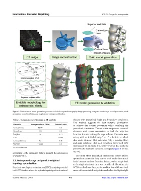
Figure 2. Finite element model generation processes included computed tomography image processing, computer-aided design model generation, mesh
generation, model validation, and endplate morphology modification.
Table 1. Materials properties used in FE analysis objects with prescribed loads and boundary conditions.
This method suggests the best material distribution
Materials Young’s modulus (MPa) Poission’s ratio to achieve the desired properties while satisfying the
Cortical bone 12000 0.3 prescribed constraints. The optimization process removed
Cancellous 100 0.2 elements with stress constraints to find the objective
Endplate 24 0.25 function for minimizing the cage volume. Elements were
Core 1 0.499 set up with an initial density. The L3 – L4 intervertebral
Annulus fibrosus 4.2 0.45 disc under flexion (-Ry), extension (+Ry), bending (Rx),
and axial rotation (-Rz) load condition performed STO
Ti6Al4V 110000 0.3 individually to calculate if the intervertebral disc could be
FE: Finite element
preserved to maintain sufficient strength (Figure 3 for Rx,
Ry, Rz).
according to the measured data to present the subsidence
characteristics. However, these individual simulations cannot reflect
optimal structures for daily actives with multi-directional
2.3. Osteoporotic cage design with weighted loads because in these four simulations, only a single load
topology optimization at the single simulated time was considered. Therefore, the
Standard topological optimization (STO) analysis provided WTO method was then performed for four different load
in ANSYS is a technique for optimizing designs for structural cases with associated weights to recalculate the lightweight
Volume 9 Issue 3 (2023) 413 https://doi.org/10.18063/ijb.697