
Page 425 - IJB-9-3
P. 425
International Journal of Bioprinting 3DP PILF cage for osteoporotic
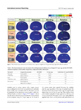
Figure 7. The von Mises stress distributions of L3 inferior and L4 superior endplates for CS-type and P-type cages under all load conditions.
Table 3. The biomechanical in vitro test result of the yielding load and stiffness of our designed CS‑type cage and the ISO 23089
standard acceptance criteria under compression, compression‑shear and torsion
Test model Comparative parameter ISO 23089 CS‑type cage Safety factor (CS‑type/ISO23089)
Static axial Yield load (N) 6317 134643 21.3
compression Stiffness (N/mm) 5914 70080 11.8
Static Yield load (N) 1996 23904 12.0
compression-shear Stiffness (N/mm) 1435 19841 13.8
Static torsion Yield load (N-m) 7 19.8 2.8
Stiffness (N-mm/degree) 1 3.5 3.5
endplate were in surface contact with a larger contact the contact point (star symbol) between the endplate
area, enabling the stress to be transmitted more uniformly. and the cage regardless of the type of applied loads. The
These results were consistent with the literature and can maximum stress value for the P-type cage was significantly
be explained by the maximum stress location under four higher than that for the CS-type cage. The endplate stress
different loads, as shown in Figure 7 [22,23] . Figure 7 shows concentration using the CS-type cage was less obvious, and
that the stress concentration and maximum stress positions it was in a position with larger contact area under different
of the endplate using the P-type cage can be found in applied loads, that is, at the anterior side under flexion, at
Volume 9 Issue 3 (2023) 417 https://doi.org/10.18063/ijb.697